Hitachi HDS728080PLAT20 Specifications - Page 59
logical head default - jumper
 |
UPC - 829686000094
View all Hitachi HDS728080PLAT20 manuals
Add to My Manuals
Save this manual to your list of manuals |
Page 59 highlights
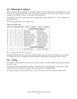
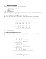
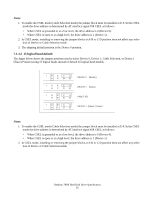
Notes: 1. To enable the CSEL mode (Cable Selection mode) the jumper block must be installed at E-F. In the CSEL mode the drive address is determined by AT interface signal #28 CSEL as follows: • When CSEL is grounded or at a low level, the drive address is 0 (Device 0). • When CSEL is open or at a high level, the drive address is 1 (Device 1). 2. In CSEL mode, installing or removing the jumper blocks at A-B or C-D position does not affect any selection of Device or Cable Selection mode. 3. The shipping default position is the Device 0 position. 7.1.4.2 15 logical head default The figure below shows the jumper positions used to select Device 0, Device 1, Cable Selection, or Device1 (Slave) Present setting 15 logical heads instead of default 16 logical head models. IGECA HFDB IGECA HFDB IGECA HFDB IGECA HFDB DEVICE 0 (Master) DEVICE 1 (Slave) CABLE SEL DEVICE 1 (Slave) Present Notes: 1. To enable the CSEL mode (Cable Selection mode) the jumper block must be installed at E-F. In the CSEL mode the drive address is determined by AT interface signal #28 CSEL as follows: • When CSEL is grounded or at a low level, the drive address is 0 (Device 0). • When CSEL is open or at a high level, the drive address is 1 (Device 1). 2. In CSEL mode, installing or removing the jumper blocks at A-B or C-D position does not affect any selection of Device or Cable Selection mode. Deskstar 7K80 Hard Disk Drive Specification 55
-
 1
1 -
2
-
3
-
4
-
5
-
6
-
7
-
8
-
9
-
10
-
11
-
12
-
13
-
14
-
15
-
16
-
17
-
18
-
19
-
20
-
21
-
22
-
23
-
24
-
25
-
26
-
27
-
28
-
29
-
30
-
31
-
32
-
33
-
34
-
35
-
36
-
37
-
38
-
39
-
40
-
41
-
42
-
43
-
44
-
45
-
46
-
47
-
48
-
49
-
50
-
51
-
52
-
53
-
 54
54 -
 55
55 -
 56
56 -
 57
57 -
 58
58 -
 59
59 -
 60
60 -
 61
61 -
 62
62 -
 63
63 -
 64
64 -
65
-
66
-
67
-
68
-
69
-
70
-
71
-
72
-
73
-
74
-
75
-
76
-
77
-
78
-
79
-
80
-
81
-
82
-
83
-
84
-
85
-
86
-
87
-
88
-
89
-
90
-
91
-
92
-
93
-
94
-
95
-
96
-
97
-
98
-
99
-
100
-
101
-
102
-
103
-
104
-
105
-
106
-
107
-
108
-
109
-
110
-
111
-
112
-
113
-
114
-
115
-
116
-
117
-
118
-
119
-
120
-
121
-
122
-
123
-
124
-
125
-
126
-
127
-
128
-
129
-
130
-
131
-
132
-
133
-
134
-
135
-
136
-
137
-
138
-
139
-
140
-
141
-
142
-
143
-
144
-
145
-
146
-
147
-
148
-
149
-
150
-
151
-
152
-
153
-
154
-
155
-
156
-
157
-
158
-
159
-
160
-
161
-
162
-
163
-
164
-
165
-
166
-
167
-
168
-
169
-
170
-
171
-
172
-
173
-
174
-
175
-
176
-
177
-
178
-
179
-
180
-
181
-
182
-
183
-
184
-
185
-
186
-
187
-
188
-
189
-
190
-
191
-
192
-
193
-
194
-
195
-
196
-
197
-
198
-
199
-
200
-
201
-
202
-
203
-
204
-
205
-
206
-
207
-
208
-
209
-
210
-
211
-
212
-
213
-
214
-
215
-
216
-
217
-
218
-
219
-
220
-
221
-
222
-
223
-
224
-
225
-
226
-
227
-
228
-
229
-
230
-
231
-
232
-
233
-
234
-
235
-
236
-
237
-
238
-
239
-
240
-
241
-
242
-
243
-
244
-
245
-
246
-
247
-
248
-
249
-
250
-
251
-
252
-
253
-
254
-
255
-
256
-
257
-
258
 |
 |