IBM 26K6477 User Guide - Page 35
Addressing, association, diagrams
 |
View all IBM 26K6477 manuals
Add to My Manuals
Save this manual to your list of manuals |
Page 35 highlights
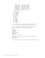
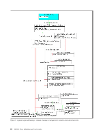
Further discussion of addressing associations can be found in "Addressing association diagrams." For details on nonaddressing associations, see "SMASH Proxy nonaddressing associations and supported physical and logical targets" on page 64. Addressing association diagrams The following diagrams show all objects, UFcTs, and addressing associations supported by the SMASH Proxy. Each path from the root of a tree to one of the intermediate or terminal leaves represents a SMASH target. The root of the tree, /admin1, can be omitted from the target path. For example, in Figure 3 on page 20, the following targets are all possible: / /hdwr1 /hdwr1/chassis1 /hdwr1/chassis1/bladepkg1 /hdwr1/chassis1/bladepkg1/card1 /hdwr1/chassis1/bladepkg1/bladexpkg1 /hdwr1/chassis1/modulepkg1 /hdwr1/chassis1/fanpkg1 /hdwr1/chassis1/pwrpkg1 /hdwr1/chassis1/pkg1 /hdwr1/chassis1/storagepkg1 You can interpret Figure 4 on page 22 through Figure 7 on page 28 in a similar manner. Note: There can be multiple chassis and multiple blades, power supplies, fans, inside a chassis. Thus, although the targets above are all listed with the UFiT instance number of 1, for example, chassis1, other UFiT instance numbers might also be possible depending on the chassis in your environment. For example, if you have two chassis and the second chassis has four power supplies, then /hdwr1/chassis2/pwrpkg4 is a valid target. Chapter 3. Using the SMASH CLP command line 19
-
 1
1 -
2
-
3
-
4
-
5
-
6
-
7
-
8
-
9
-
10
-
11
-
12
-
13
-
14
-
15
-
16
-
17
-
18
-
19
-
20
-
21
-
22
-
23
-
24
-
25
-
26
-
27
-
28
-
29
-
 30
30 -
 31
31 -
 32
32 -
 33
33 -
 34
34 -
 35
35 -
 36
36 -
 37
37 -
 38
38 -
 39
39 -
 40
40 -
41
-
42
-
43
-
44
-
45
-
46
-
47
-
48
-
49
-
50
-
51
-
52
-
53
-
54
-
55
-
56
-
57
-
58
-
59
-
60
-
61
-
62
-
63
-
64
-
65
-
66
-
67
-
68
-
69
-
70
-
71
-
72
-
73
-
74
-
75
-
76
-
77
-
78
-
79
-
80
-
81
-
82
-
83
-
84
-
85
-
86
-
87
-
88
-
89
-
90
-
91
-
92
-
93
-
94
-
95
-
96
-
97
-
98
-
99
-
100
-
101
-
102
-
103
-
104
-
105
-
106
-
107
-
108
-
109
-
110
-
111
-
112
-
113
-
114
-
115
-
116
-
117
-
118
-
119
-
120
-
121
-
122
-
123
-
124
-
125
-
126
-
127
-
128
-
129
-
130
-
131
-
132
-
133
-
134
-
135
-
136
-
137
-
138
-
139
-
140
 |
 |
