IBM 26K6477 User Guide - Page 88
SMASH, Proxy, supported, targets, associated, command, target, properties
 |
View all IBM 26K6477 manuals
Add to My Manuals
Save this manual to your list of manuals |
Page 88 highlights
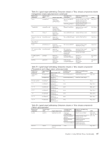
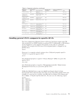
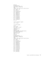
where each system object shows up with its most specific UFcT. Given the output above, if a user wants to target a particular switch, he or she can specify: show /modular1/switch3 He or she cannot specify: show /modular1/system3 Note: A UFiT with system always only refers to a blade. That is, although system* can show switches and MMs, system1, system2...systemX are always blades. General UFcTs are identified in the tables found in "SMASH Proxy supported targets (by UFcT) and associated command target properties." SMASH Proxy supported targets (by UFcT) and associated command target properties Command target properties are attributes that can contain values associated with a target that the SMASH Proxy needs to process the command. Command target properties identify properties of the target's class that the command retrieves or modifies. For example, Table 42 displays the properties for the UFcT target system that are, by default, displayed when running a show command against that target. Table 42. system UFcT properties UFcT Property system CreationClassName Name NameFormat HealthState Property type string string string uint16 ValueMap StatusDescriptons OperationalStatus Dedicated EnabledState RequestedState string[] uint16[] ValueMap uint16[] ValueMap uint16 ValueMap uint16 ValueMap Possible values for property "IICM_ComputerSystem" [Chassis Name]|[Instance Tag] ″Other″ 0 ("Unknown"), 5 ("OK"), 10 ("Degraded/Warning"), 20 ("Major Failure") "Powered On", "Powered Off" 1 ("Other") 0 ("Not Dedicated") 2 ("Enabled"), 3 ("Disabled") 2 ("Enabled"), 3 ("Disabled") Note: The Chassis Name (as seen above in [Chassis Name]|[Instance Tag]) is the name given to the BladeCenter server in the Web interface (MM Control->General Settings->MM Information->Name; see Figure 14 on page 73) and might or might not be the same as the Ethernet host name given to the BladeCenter server. In addition to this fact, it is important that you make sure that the name you select for each chassis is unique. 72 SMASH Proxy Installation and User's Guide
-
 1
1 -
2
-
3
-
4
-
5
-
6
-
7
-
8
-
9
-
10
-
11
-
12
-
13
-
14
-
15
-
16
-
17
-
18
-
19
-
20
-
21
-
22
-
23
-
24
-
25
-
26
-
27
-
28
-
29
-
30
-
31
-
32
-
33
-
34
-
35
-
36
-
37
-
38
-
39
-
40
-
41
-
42
-
43
-
44
-
45
-
46
-
47
-
48
-
49
-
50
-
51
-
52
-
53
-
54
-
55
-
56
-
57
-
58
-
59
-
60
-
61
-
62
-
63
-
64
-
65
-
66
-
67
-
68
-
69
-
70
-
71
-
72
-
73
-
74
-
75
-
76
-
77
-
78
-
79
-
80
-
81
-
82
-
 83
83 -
 84
84 -
 85
85 -
 86
86 -
 87
87 -
 88
88 -
 89
89 -
 90
90 -
 91
91 -
 92
92 -
 93
93 -
94
-
95
-
96
-
97
-
98
-
99
-
100
-
101
-
102
-
103
-
104
-
105
-
106
-
107
-
108
-
109
-
110
-
111
-
112
-
113
-
114
-
115
-
116
-
117
-
118
-
119
-
120
-
121
-
122
-
123
-
124
-
125
-
126
-
127
-
128
-
129
-
130
-
131
-
132
-
133
-
134
-
135
-
136
-
137
-
138
-
139
-
140
 |
 |
