IBM DTCA-24090 Hard Drive Specifications - Page 170
Write Long 32h/33h
 |
View all IBM DTCA-24090 manuals
Add to My Manuals
Save this manual to your list of manuals |
Page 170 highlights
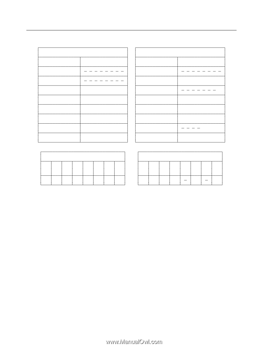
12.35 Write Long (32h/33h) Command Block Output Registers Register 76543210 Data Feature Sector Count 0 0 0 0 0 0 0 1 Sector Number V V V V V V V V Cylinder Low V V V V V V V V Cylinder High V V V V V V V V Device/Head 1L1DHHHH Command 0011001R Command Block Input Registers Register 76543210 Data Error ...See Below... Sector Count V Sector Number V V V V V V V V Cylinder Low V V V V V V V V Cylinder High V V V V V V V V Device/Head HHHH Status ...See Below... Error Register 76543210 CRC UNC 0 IDN 0 ABT T0N AMN 000V0V00 Status Register 76543210 BSY RDY DF DSC DRQ COR IDX ERR 0VVV 0 V Figure 105. Write Long Command (32h/33h) The Write Long command transfers the data and the ECC bytes of the designated one sector from the host to the device, then the data and the ECC bytes are written to the disk media. After 512 bytes of data have been transferred, the device will keep setting D R Q = 1 to indicate that the device is ready to receive the ECC bytes from the host. The data is transferred 16 bits at a time, and the ECC bytes are transferred 8 bits at a time. The number of ECC bytes are 4 or 28 according to setting of Set Feature option. The default number after power on is 4 bytes. Output Parameters To The Device Sector Count The number of continuous sectors to be transferred. The Sector Count must be set to one. Sector Number The sector number of the sector to be transferred. ( L = 0 ) In LBA mode, this register contains LBA bits 0 - 7. ( L = 1 ) Cylinder High/Low The cylinder number of the sector to be transferred. ( L = 0 ) In LBA mode, this register contains LBA bits 8 - 15 (Low), 16 - 23 (High). ( L = 1 ) H The head number of the sector to be transferred. ( L = 0 ) In LBA mode, this register contains LBA bits 24 - 27. ( L = 1 ) R The retry bit. If set to one, then retries are disabled. 162 OEM Specifications of DTCA-2xxxx 2.5 inch H D D
-
 1
1 -
2
-
3
-
4
-
5
-
6
-
7
-
8
-
9
-
10
-
11
-
12
-
13
-
14
-
15
-
16
-
17
-
18
-
19
-
20
-
21
-
22
-
23
-
24
-
25
-
26
-
27
-
28
-
29
-
30
-
31
-
32
-
33
-
34
-
35
-
36
-
37
-
38
-
39
-
40
-
41
-
42
-
43
-
44
-
45
-
46
-
47
-
48
-
49
-
50
-
51
-
52
-
53
-
54
-
55
-
56
-
57
-
58
-
59
-
60
-
61
-
62
-
63
-
64
-
65
-
66
-
67
-
68
-
69
-
70
-
71
-
72
-
73
-
74
-
75
-
76
-
77
-
78
-
79
-
80
-
81
-
82
-
83
-
84
-
85
-
86
-
87
-
88
-
89
-
90
-
91
-
92
-
93
-
94
-
95
-
96
-
97
-
98
-
99
-
100
-
101
-
102
-
103
-
104
-
105
-
106
-
107
-
108
-
109
-
110
-
111
-
112
-
113
-
114
-
115
-
116
-
117
-
118
-
119
-
120
-
121
-
122
-
123
-
124
-
125
-
126
-
127
-
128
-
129
-
130
-
131
-
132
-
133
-
134
-
135
-
136
-
137
-
138
-
139
-
140
-
141
-
142
-
143
-
144
-
145
-
146
-
147
-
148
-
149
-
150
-
151
-
152
-
153
-
154
-
155
-
156
-
157
-
158
-
159
-
160
-
161
-
162
-
163
-
164
-
 165
165 -
 166
166 -
 167
167 -
 168
168 -
 169
169 -
 170
170 -
 171
171 -
 172
172 -
 173
173 -
 174
174 -
 175
175 -
176
-
177
-
178
-
179
-
180
-
181
-
182
-
183
-
184
-
185
-
186
-
187
-
188
-
189
-
190
 |
 |