Intel 2011B Configuration Guide - Page 10
Extending a Network's Radio Coverage, One-Hop Wireless Network Example, Two-Hop Wireless
 |
UPC - 735858150187
View all Intel 2011B manuals
Add to My Manuals
Save this manual to your list of manuals |
Page 10 highlights
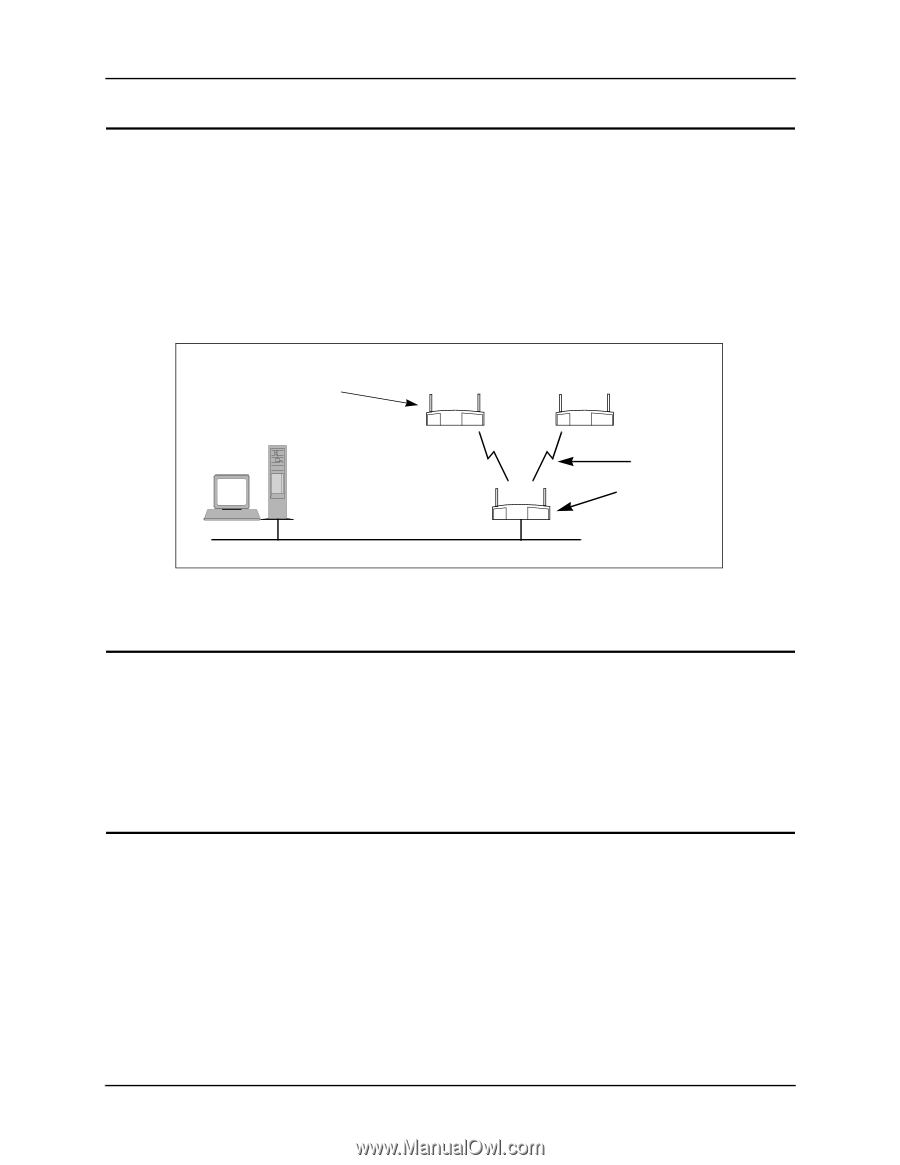
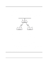
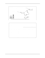
Chapter 2. Extending a Network's Radio Coverage Chapter 2. Extending a Network's Radio Coverage This section covers examples for extending the radio coverage of a single Ethernet network with one-hop and two-hop wireless AP operations. The term "hop" refers to the direct communications link between two nodes of a network. With regard to wireless AP operations, the number of hops refers to the number of direct links through which a message passes between the root access point and a particular designated WLAP. Examples of one-hop and two-hop operations are shown in Figure 2-1 and Figure 2-2. The basic settings for the access points are covered in the previous sections. In the following network diagram examples, the root access point is labeled A, and the two designated WLAPs are labeled B and C. For reference, the MAC addresses are included in the diagrams and example screens. HOST.CDR, FRAME WLAP Manual BSS ID of B and C set to MAC address of A Host Computer 00:A0:F8:8B:71:45 B Root access point A 00:A0:F8:93:C5:B5 WLAP Priority = 7000 Ethernet 00:A0:F8:94:C3:64 C One Hop WLAP Manual BSS ID of A set to its own MAC address. Figure 2-1: Wireless AP Network with One Hop 2.1 One-Hop Wireless Network Example The example in Figure 2-1 extends a network's radio coverage with one hop between the root access point A and the two designated WLAPs B and C. To configure the one-hop network, set the WLAP Manual BSS ID on the root access point to its own MAC address. In addition, set the WLAP Manual BSS ID on access point B and C to the MAC address of access point A. The RF Configuration screen for the root access point A is shown in Figure 2-3. 2.2 Two-Hop Wireless Network Example The example in Figure 2-2 extends a network's radio coverage with two hops. In this network, there is one hop between the root access point A and designated WLAP B, then another hop between WLAP B and the other designated WLAP C. To configure a two-hop network, set the WLAP Manual BSS ID on access point C to the MAC address of access point B and the WLAP Manual BSS ID on B to the MAC address of the root access point A. The Manual BSS ID for the root access point A is set to its own MAC address. The RF Configuration screen in Figure 2-3 shows the WLAP Manual BSS ID setting for access point C. The RF Configuration screens for the other two access points are the same except the WLAP Manual BSS IDs would be set to 00:A0:F8:93:C5:B5 and the WLAP Priority for access point A would be set to 7000. 4 Configuring Access Point Bridging and Repeating (WLAP Mode)
-
 1
1 -
2
-
3
-
4
-
 5
5 -
 6
6 -
 7
7 -
 8
8 -
 9
9 -
 10
10 -
 11
11 -
 12
12 -
 13
13 -
 14
14 -
 15
15 -
16
-
17
-
18
-
19
-
20
-
21
-
22
-
23
-
24
-
25
-
26
-
27
-
28
-
29
-
30
-
31
-
32
-
33
-
34
-
35
-
36
-
37
-
38
-
39
-
40
-
41
-
42
-
43
-
44
 |
 |