Intel 2011B Configuration Guide - Page 14
Observing the Access Point's LED Indicators - lan access point
 |
UPC - 735858150187
View all Intel 2011B manuals
Add to My Manuals
Save this manual to your list of manuals |
Page 14 highlights
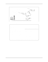
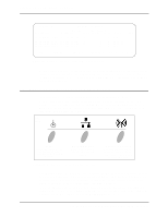
Chapter 3. Verifying Wireless AP Operations Access Point A Known Access Points MAC Address Net_ID: Warehouse 1 IP Address CH HST HSQ MUS KBIOS FW_Ver 00:A0:F8:93:C5:B5 157.235.55.199 3 - - 0 0 02.51-11 00:A0:F8:8B:71:45 157.235.55.60 1- - 0 00:A0:F8:94:C3:64 157.235.55.198 11 - - 0 00:A0:F8:94:C2:04 157.235.55.53 1- - 0 0 02.51-11 0 02.51-11 0 02.51-11 Away Echo-[F1] Delete-[F2] Next-[F3] Previous-[F4] Switch Exit-[ESC] Figure 3-3: Known Access Points Showing WLAPs Plus Other With this screen displayed, you can run an echo test, which performs a PING operation between the current access point and any of the listed radio-or wired-linked access points. To do this, you use the Tab key to highlight the access point you wish to PING. Then press F1, followed by the Enter key to start the echo test. 3.3 Observing the Access Point's LED Indicators The access point's LED indicators and their basic functions are shown in Figure 3-4. As an access point proceeds through the various states of a wireless AP operation, the LEDs provide certain status indications. The Intel® PRO/Wireless 2011/2011B LAN Product Reference Guides describe how the LED indicators are displayed during the several wireless AP operating states from Initializing through Functional. ICON GIF FILES & FRAME Power Flashes during power-up sequence (reset). Continuously on during operation. Wired LAN Activity Flashes when data is transferred on wired network. Figure 3-4: Access Point LED Indicators and Functions Wireless LAN Activity Flickers when access point sends out beacon signals, and transfers data to and from a mobile unit. During normal operation, it may be difficult to observe the LED indicator status because the states exists for only a very short time. During an abnormal operation, the access point may remain in a particular state permanently or for a significant length of time. In this situation, you can easily determine abnormal operation from the status of the LED indicators. The following subsections cover two of the wireless AP states that you can easily determine by observing the LED indicators. These two states are: Functional and Send Probe. One of these states is displayed as the Current State entry on the WLAP RF Statistics screen. 8 Configuring Access Point Bridging and Repeating (WLAP Mode)
-
 1
1 -
2
-
3
-
4
-
5
-
6
-
7
-
8
-
 9
9 -
 10
10 -
 11
11 -
 12
12 -
 13
13 -
 14
14 -
 15
15 -
 16
16 -
 17
17 -
 18
18 -
 19
19 -
20
-
21
-
22
-
23
-
24
-
25
-
26
-
27
-
28
-
29
-
30
-
31
-
32
-
33
-
34
-
35
-
36
-
37
-
38
-
39
-
40
-
41
-
42
-
43
-
44
 |
 |