Intel 2011B Configuration Guide - Page 38
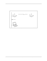
Procedure for Aligning Directional Antennas
 |
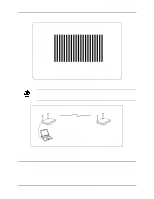
UPC - 735858150187
View all Intel 2011B manuals
Add to My Manuals
Save this manual to your list of manuals |
Page 38 highlights
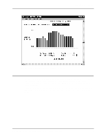
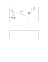
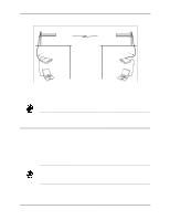
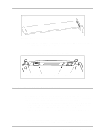
Chapter 6. RF Link Test YAGIANT.WMF Figure 6-13: Exampel of a Directional Antenna 3. Connect the access point to a computer through a serial cable and turn on the access point. The DC power connector is shown in Figure 6-14. 4. With the Access Point Installation screen displayed on the computer, set the Antenna Selection option to Primary Only. Press F1 to save the setting, then reset the access point. Refer to the next subsection for the antenna alignment procedure. DSAPBOTCN2.WMF Antenna 2 Connector Serial Port Connector Figure 6-14: Access Point Connectors DC Power Connector Antenna 1 Connector 6.6.2 Procedure for Aligning Directional Antennas After setting up the equipment, follow these steps for aligning directional antennas connected to the bridging access points. At each location, a technician performs the procedure. Align one antenna first, and then align the other. As the technicians position the antenna and run the RF Link Test, they need to communicate with each other using two-way radios or cell phones. Other equipment you may need is covered in 6.6.3: Additional Suggestions on Antenna Alignment. 1. Attempt to point the antennas toward each other so that the access points communicate with each other through a wireless access point operation. Information on verifying the wireless access point operation is covered in 6.3: Preparing for the RF Link Test. 2. Make sure the Rate Control on the RF Configurations screen is set to Required for all four rates (Figure 6-15). This is recommended for access points that are performing a bridging function. 3. If antennas are over a mile apart, set the Extended Range on the RF Configuration screen to the appropriate distance setting. Type in the closest whole number in miles that matches the distance between antennas. This setting allows for the timing delays for distances over 1 mile. 32 Configuring Access Point Bridging and Repeating (WLAP Mode)
-
 1
1 -
2
-
3
-
4
-
5
-
6
-
7
-
8
-
9
-
10
-
11
-
12
-
13
-
14
-
15
-
16
-
17
-
18
-
19
-
20
-
21
-
22
-
23
-
24
-
25
-
26
-
27
-
28
-
29
-
30
-
31
-
32
-
 33
33 -
 34
34 -
 35
35 -
 36
36 -
 37
37 -
 38
38 -
 39
39 -
 40
40 -
 41
41 -
 42
42 -
 43
43 -
44
 |
 |
