Intel 2011B Configuration Guide - Page 20
on RF Configuration Screen. On designated WLAPs B and C, set the WLAP Mode
 |
UPC - 735858150187
View all Intel 2011B manuals
Add to My Manuals
Save this manual to your list of manuals |
Page 20 highlights
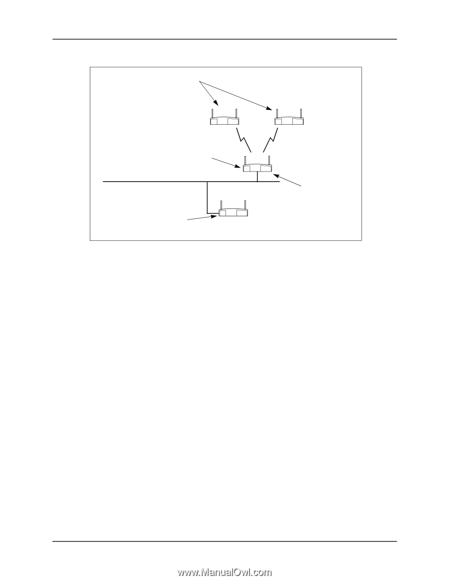
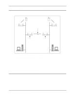
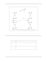
Chapter 4. Using the Link Required Option WLAP Mode = Link Required. WLAP Priority = 8000. WLAP Manual BSS ID set to access point A's preferred MAC address (01:A0:F8:93:C5:B5). Ethernet Timeout = 0. WLAP Mode = Enabled. WLAP Priority = 7000. WLAP Manual BSS ID set to its own MAC address (00:A0:F8:93:C5:B5). Ethernet Timeout = 1. FRAME B C A Ethernet WLAP Mode = Enabled. WLAP Priority = 6000. WLAP Manual BSS ID set to its own MAC address. Ethernet Timeout = 1. If Ethernet connection is lost, access point D becomes new root access point. D Figure 4-5: Network with Backup Root Access Point Access point settings for the example in Figure 4-5 are described as follows: Basic Settings. Make the settings previously described in 1.1: Basic Settings for Access Points. WLAP Mode on RF Configuration Screen. On designated WLAPs B and C, set the WLAP Mode to Link Required. This causes the WLAPs to search for another access point with an Ethernet connection in the event the root access point loses its Ethernet connection. WLAP Mode for access points A and D is set to Enabled. WLAP Priority on RF Configuration Screen. On access point A, make sure its WLAP Priority is set to a lower number (e.g., 7000) than the two WLAPs. On access point D, make sure its WLAP Priority is set to a lower number (e.g., 6000) than the other access points. The lower priority number ensures that access point D is recognized as the new root access point in the event access point A loses its Ethernet connection. WLAP Manual BSS ID on RF Configuration Screen. On designated WLAPs B and C, set the WLAP Manual BSS ID to the "preferred" MAC address of the root access point A. To enter a preferred MAC address, change the first two numbers of the MAC address from 00 to 01; for example, 01:A0:F8:8D:25:F2. Using a preferred MAC address not only causes WLAPs B and C to associate with the root access point A, it also allows them to roam to another access point if the Ethernet connection to access point A is lost. Ethernet Timeout on System Configuration Screen. Set the Ethernet Timeout to 1 on the two access points connected to the Ethernet (access points A and D). On WLAPs B and C, set the Ethernet Timeout to the default value of 0. With its Timeout set to 1, access point A detects a broken Ethernet connection and turns off its radio to allow the designated WLAPs B and C to search for another access point (e.g., access point D). Likewise, if access point D becomes the root, it would perform in the same way if it loses its Ethernet connection. An example System Configuration screen is shown in Figure 4-6. 14 Configuring Access Point Bridging and Repeating (WLAP Mode)
-
 1
1 -
2
-
3
-
4
-
5
-
6
-
7
-
8
-
9
-
10
-
11
-
12
-
13
-
14
-
 15
15 -
 16
16 -
 17
17 -
 18
18 -
 19
19 -
 20
20 -
 21
21 -
 22
22 -
 23
23 -
 24
24 -
 25
25 -
26
-
27
-
28
-
29
-
30
-
31
-
32
-
33
-
34
-
35
-
36
-
37
-
38
-
39
-
40
-
41
-
42
-
43
-
44
 |
 |