Intel 2011B Configuration Guide - Page 22
Bridging Two Ethernet Networks, Verifying the Bridging Operation
 |
UPC - 735858150187
View all Intel 2011B manuals
Add to My Manuals
Save this manual to your list of manuals |
Page 22 highlights
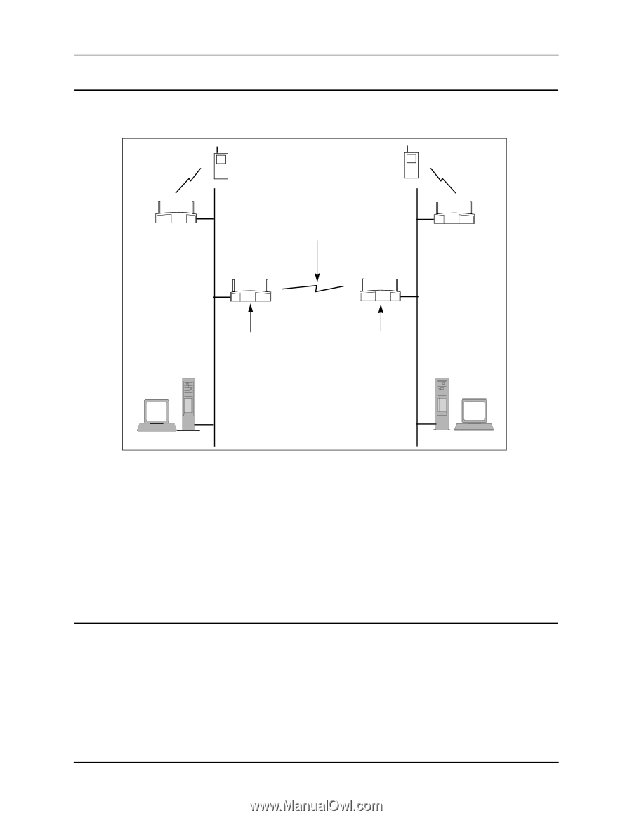
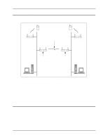
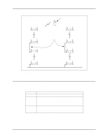
Chapter 5. Bridging Two Ethernet Networks Chapter 5. Bridging Two Ethernet Networks As mentioned previously, you can use the wireless AP bridging feature to obtain a wireless connection between two Ethernet networks. An example of this is shown in Figure 5-1. HOST.CDR, FRAME C 00:A0:F8:94:C3:64 WLAP Mode Disabled D Wireless Link 00:A0:F8:94:C2:04 WLAP Mode Disabled Root A B Ethernet Ethernet Host Computer 00:A0:F8:93:C5:B5 WLAP Mode Enabled. WLAP Manual BSS ID set to MAC address of root access point B. 00:A0:F8:8B:71:45 WLAP Mode Enabled. WLAP Manual BSS ID set to its own MAC address Host Computer Figure 5-1: Bridging Two Ethernet Networks with Wireless AP In the example, access points A and B have their WLAP Mode set to Enabled and provide the link between the two Ethernet networks. The WLAP Manual BSS ID for access point A is set to the MAC address of root access point B. The WLAP Manual BSS ID for root access point B is set to its own MAC address. Access point B is the root access point because its MAC address (00:A0:F8:8B:71:45) is lower than that of access point A (00:A0:F8:93:C5:B5). The WLAP Priority for these access points is set to the default value, 8000. Also, in the example, all access points have their Ethernet Timeout set to the default value of zero, and access points C and D have their WLAP Mode disabled. 5.1 Verifying the Bridging Operation As in the other wireless AP configurations, you can verify the network bridging operating by viewing the WLAP RF Statistics screen and the Known Access Points screen. To determine which access points are operating in the wireless AP mode, view the WLAP RF Statistics screen. The example screen in Figure 5-2 shows access point A with a Current State of Functional and the forwarding of data (FWD) to the MAC address of access point B. Likewise, the screen viewed on access point B would show the forwarding of data to access point A. This verifies the wireless link between the two Ethernet networks in the example of Figure 5-1. 16 Configuring Access Point Bridging and Repeating (WLAP Mode)
-
 1
1 -
2
-
3
-
4
-
5
-
6
-
7
-
8
-
9
-
10
-
11
-
12
-
13
-
14
-
15
-
16
-
 17
17 -
 18
18 -
 19
19 -
 20
20 -
 21
21 -
 22
22 -
 23
23 -
 24
24 -
 25
25 -
 26
26 -
 27
27 -
28
-
29
-
30
-
31
-
32
-
33
-
34
-
35
-
36
-
37
-
38
-
39
-
40
-
41
-
42
-
43
-
44
 |
 |