Intel 2011B Configuration Guide - Page 37
Setting Up for the Antenna Alignment Procedure
 |
UPC - 735858150187
View all Intel 2011B manuals
Add to My Manuals
Save this manual to your list of manuals |
Page 37 highlights
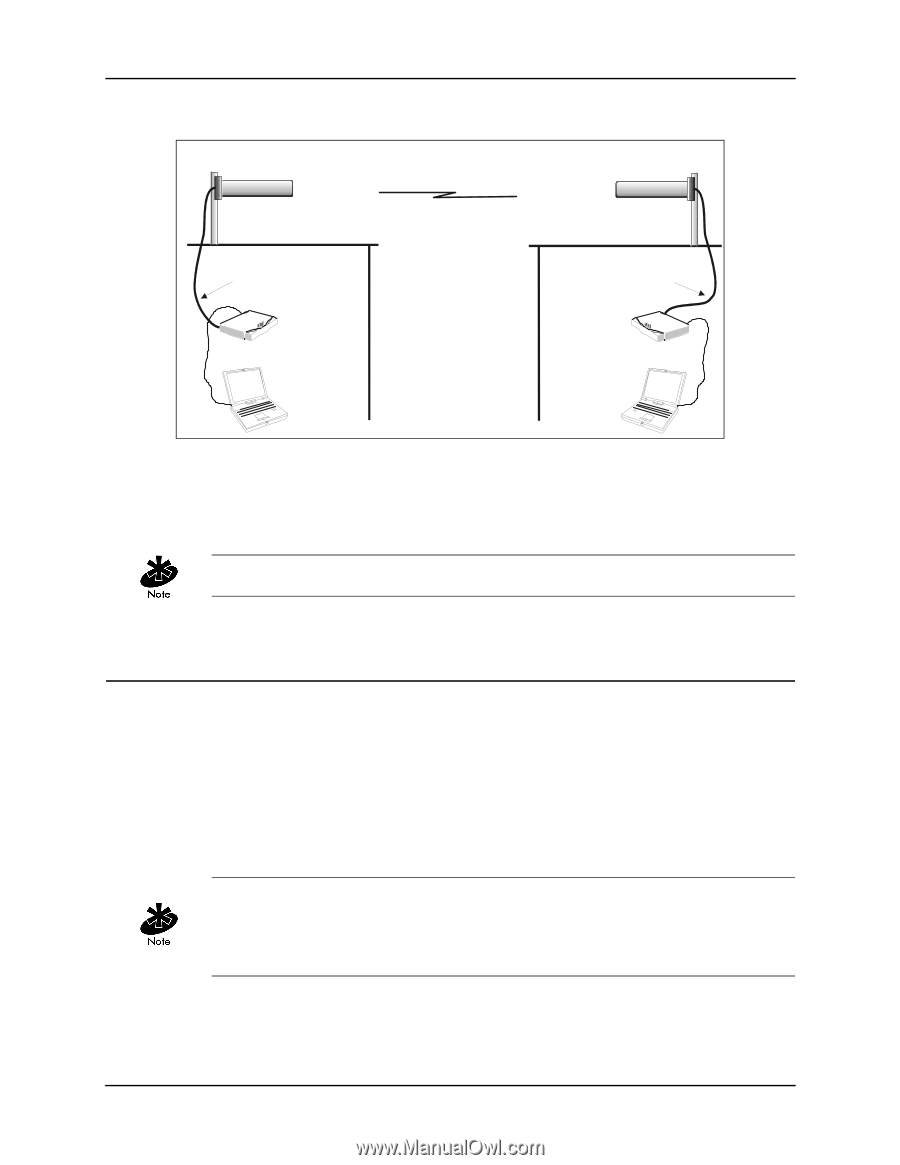
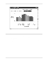
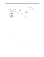
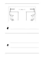
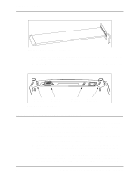
Chapter 6. RF Link Test Directional Antenna on Roof of Building A Wireless AP Link Antenna Cable Directional Antenna on Roof of Building B Antenna Cable Access Point A Computer with Serial Cable Access Point B Computer with Serial Cable RFLINKSYS.W MF Figure 6-12: Example Setup for Using RF Link Test to Align Antennas The alignment procedure is to point the antennas toward each other so that the RF Link Test for each access point shows the maximum RSSI reading. The antenna positioning is further refined by reducing the access point's radio power, while maintaining the maximum RSSI reading. Some access points support the radio power control feature; others do not support this feature. This procedure is covered in the following subsections. 6.6.1 Setting Up for the Antenna Alignment Procedure Follow these steps to set up the bridging access points. An example setup diagram is shown in Figure 6-12. 1. Install the directional antennas so that nothing obstructs the line of sight between them. For best results, mount each antenna on a pole on an elevated location such as the roof of a building. An example of a directional antenna is shown in Figure 6-13. 2. Connect the antenna cable to the access point's Antenna 1 connector, sometimes referred to as the Primary connector. As shown in Figure 6-14, this is the connector on the right as you face the rear of the access point. If the standard antenna cable is not long enough, use a special low-loss antenna cable. The low-loss antenna cable is custom made for a particular installation. It usually connects to the access point through an adapter cable. Length of the low-loss cable may be up to 60 feet. Only site survey or cable specialists should make custom antenna cables of this type. Configuring Access Point Bridging and Repeating (WLAP Mode) 31
-
 1
1 -
2
-
3
-
4
-
5
-
6
-
7
-
8
-
9
-
10
-
11
-
12
-
13
-
14
-
15
-
16
-
17
-
18
-
19
-
20
-
21
-
22
-
23
-
24
-
25
-
26
-
27
-
28
-
29
-
30
-
31
-
 32
32 -
 33
33 -
 34
34 -
 35
35 -
 36
36 -
 37
37 -
 38
38 -
 39
39 -
 40
40 -
 41
41 -
 42
42 -
43
-
44
 |
 |