Intel 2011B Configuration Guide - Page 27
Using the Ethernet Timeout Setting 4
 |
UPC - 735858150187
View all Intel 2011B manuals
Add to My Manuals
Save this manual to your list of manuals |
Page 27 highlights
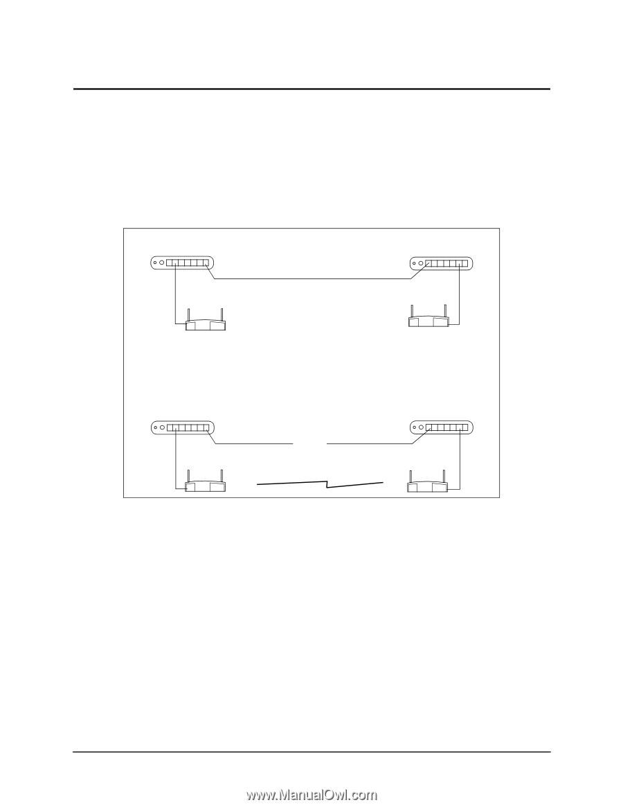
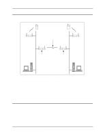
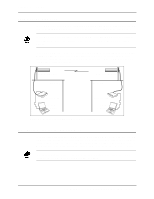
5.3 Using the Ethernet Timeout Setting 4 Ethernet Timeout setting 4 on System Configuration screen is used in special network configurations such as the one shown in Figure 5-7. In this network, the Timeout setting 4 allows access point B to detect a missing WLAP-Alive BPDU message if the Ethernet connection is lost between the two network hubs. When this occurs, access point B resets and makes a wireless connection with access point A. If the Ethernet connection is restored, access point B resets and the wireless connection is terminated. As shown in Figure 5-7, Ethernet Timeout is set to 2 for access point A and to 4 for access point B. Both access points have the WLAP Mode set to Enabled, WLAP Priority set to 8000 (default), and WLAP Manual BSS ID set to zero (default). FRAME Hub 1 Ethernet Connection Hub 2 A Ethernet Timeout = 2 WLAP Mode = Enabled WLAP Priority = 8000 WLAP Manual BSS ID = 0 B Ethernet Timeout = 4 WLAP Mode = Enabled WLAP Priority = 8000 WLAP Manual BSS ID = 0 Hub 1 Ethernet Connection is Lost A Wireless Connection is Made Figure 5-7: Special Network Using Ethernet Timeout 4 Hub 2 B Configuring Access Point Bridging and Repeating (WLAP Mode) 21
-
 1
1 -
2
-
3
-
4
-
5
-
6
-
7
-
8
-
9
-
10
-
11
-
12
-
13
-
14
-
15
-
16
-
17
-
18
-
19
-
20
-
21
-
 22
22 -
 23
23 -
 24
24 -
 25
25 -
 26
26 -
 27
27 -
 28
28 -
 29
29 -
 30
30 -
 31
31 -
 32
32 -
33
-
34
-
35
-
36
-
37
-
38
-
39
-
40
-
41
-
42
-
43
-
44
 |
 |