Intel 2011B Configuration Guide - Page 15
Functional State, Send Probe State - lan
 |
UPC - 735858150187
View all Intel 2011B manuals
Add to My Manuals
Save this manual to your list of manuals |
Page 15 highlights
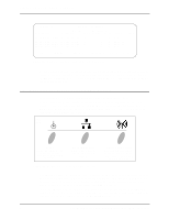
Example screens showing the Current State as "Functional" are shown in Figure 3-1 and Figure 32. An example screen showing the Current State as "Send Probe" is shown in Figure 3-5. Access Point A Current # WLAP Itf 0 Current State Priority Send Probe 8000 hex WLAP RF Statistics Root Interface Root Priority Root MAC Addr Root Path Cost 0 8000 hex 00:A0:F8:93:C5:B5 0 Wireless AP Interface Table Itf WLAP Itf Itf Path Designated Designated ID MAC Addr State Cost Root ID Cost WLAP ID Itf ID 8001 00:00:00:00:00:00 DIS 8002 00:00:00:00:00:00 DIS 8003 00:00:00:00:00:00 DIS 8004 00:00:00:00:00:00 DIS 1 800000a0f893C5B5 0 1 800000a0f893C5B5 0 1 800000a0f893C5B5 0 1 800000a0f893C5B5 0 800000a0f893C5B5 800000a0f893C5B5 800000a0f893C5B5 800000a0f893C5B5 8001 8002 8003 8004 Refresh-[F1] Timed-[F2] Previous-[F4] Exit-[ESC] Figure 3-5: Access Point in the Send Probe State 3.3.1 Functional State The Functional state means that the access point is ready for mobile units or other access points to associate with it. In this state, the LED indicators display as follows: Indicator Power Wired LAN Activity Wireless LAN Activity Activity Remains on Flashes if activity occurs Flickers rapidly Table 3-2: LED Indicators - Functional State When the access point is in the Functional state, it may or may not have successfully made a wireless AP connection. You can determine if a wireless AP connection has occurred by viewing the WLAP RF Statistic screen. If this screen lists one or more access points as being in the FWD state in the Itf State column, then the current access point has made a wireless AP connection. For examples of screens showing the FWD state, refer to Figure 3-1 and Figure 3-2. 3.3.2 Send Probe State Under certain conditions, an access point may remain in the Send Probe state (Figure 3-5) rather than continue on to the Functional state. In this state, the LED indicators display as follows: Indicator Power Wired LAN Activity Wireless LAN Activity Activity Remains on Remains off Blinks slowly (once per second) Configuring Access Point Bridging and Repeating (WLAP Mode) 9
-
 1
1 -
2
-
3
-
4
-
5
-
6
-
7
-
8
-
9
-
 10
10 -
 11
11 -
 12
12 -
 13
13 -
 14
14 -
 15
15 -
 16
16 -
 17
17 -
 18
18 -
 19
19 -
 20
20 -
21
-
22
-
23
-
24
-
25
-
26
-
27
-
28
-
29
-
30
-
31
-
32
-
33
-
34
-
35
-
36
-
37
-
38
-
39
-
40
-
41
-
42
-
43
-
44
 |
 |