Intel 2011B Configuration Guide - Page 26
Sequence of Events in Special Network
 |
UPC - 735858150187
View all Intel 2011B manuals
Add to My Manuals
Save this manual to your list of manuals |
Page 26 highlights
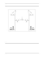
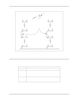
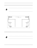
Chapter 5. Bridging Two Ethernet Networks 5.2.2 Sequence of Events in Special Network In the example network in Figure 5-4, the following events occur if access point A loses its Ethernet connection: • Access point A loses its Ethernet connection then turns off its radio. • Access point B loses the beacon message from access point A, but it keeps probing access point A (Send Probe state). • Access Point B then stops sending the WLAP-Alive-BPDU message on the cross-over Ethernet cable. • Access Point C loses the WLAP-Alive-BPDU message then turns off its radio. The Ethernet Activity LED indicator flashes approximately once every second until the Ethernet connection is restored. With a lost Ethernet connection, the WLAP RF Statistics screen displays the Current State as "WLAP Lost on Ethernet" and the Wireless Interface (Itf) State as data blocked (BLK). An example screen is shown in Figure 5-6. • Access Point D loses the beacon message from access point C, but keeps probing access point C (Send Probe state). • Mobile unit loses beacon message from access point D, then roams to access point H. Transmit+ 1 Transmit- 2 Receive+ 3 Receive- 6 1 Transmit+ 2 Transmit- 3 Receive+ 6 Receive- Pins 4, 5, 7 and 8 are not used. Figure 5-5: Wiring Connections of Cross-Over 10BaseT Cable Access Point C WLAP RF Statistics Current # WLAP Current State Priority Itf 1 WLAP Lost on Ethernet 8000 hex Root Interface Root Priority Root MAC Addr Root Path Cost 0 8000 hex 00:A0:F8:94:C3:64 0 Wireless AP Interface Table Itf WLAP Itf Itf Path Designated Designated ID MAC Addr State Cost Root ID Cost WLAP ID Itf ID 8001 00:A0:F8:94:C2:04 BLK 8002 00:00:00:00:00:00 DIS 8003 00:00:00:00:00:00 DIS 8004 00:00:00:00:00:00 DIS 1 800000a0f894C364 0 1 800000a0f894C364 0 1 800000a0f894C364 0 1 800000a0f894C364 0 800000a0f894C364 800000a0f894C364 800000a0f894C364 800000a0f894C364 8001 8002 8003 8004 Refresh-[F1] Timed-[F2] Previous-[F4] Exit-[ESC] Figure 5-6: States of Access Point C with Timeout 3 & Lost Ethernet 20 Configuring Access Point Bridging and Repeating (WLAP Mode)
-
 1
1 -
2
-
3
-
4
-
5
-
6
-
7
-
8
-
9
-
10
-
11
-
12
-
13
-
14
-
15
-
16
-
17
-
18
-
19
-
20
-
 21
21 -
 22
22 -
 23
23 -
 24
24 -
 25
25 -
 26
26 -
 27
27 -
 28
28 -
 29
29 -
 30
30 -
 31
31 -
32
-
33
-
34
-
35
-
36
-
37
-
38
-
39
-
40
-
41
-
42
-
43
-
44
 |
 |