Intel 2011B Configuration Guide - Page 23
Using the Ethernet Timeout Settings 2 & 3
 |
UPC - 735858150187
View all Intel 2011B manuals
Add to My Manuals
Save this manual to your list of manuals |
Page 23 highlights
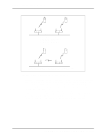
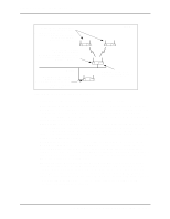
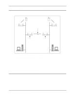
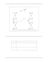
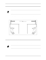
Because the other two access points C and D have their WLAP Mode disabled, their WLAP RF Statistics screen shows the Current State as Disabled and the Itf State as DIS (disabled). Access Point A Current # WLAP Itf 1 Current State Priority Functional 8000 hex WLAP RF Statistics Root Interface Root Priority Root MAC Addr Root Path Cost 1 8000 hex 00:A0:F8:8B:71:45 1 Wireless AP Interface Table Itf WLAP Itf Itf Path Designated Designated ID MAC Addr State Cost Root ID Cost WLAP ID Itf ID 8001 00:A0:F8:8B:71:45 FWD 8002 00:00:00:00:00:00 DIS 8003 00:00:00:00:00:00 DIS 8004 00:00:00:00:00:00 DIS 1 800000a0f88b7145 0 1 800000a0f893C5B5 0 1 800000a0f893C5B5 0 1 800000a0f893C5B5 0 800000a0f88b7145 800000a0f893C5B5 800000a0f893C5B5 800000a0f893C5B5 8001 8002 8003 8004 Refresh-[F1] Timed-[F2] Previous-[F4] Exit-[ESC] Figure 5-2: Verifying Wireless AP for Bridging Networks From any of the access points, you can view the Known Access Points screen to verify that all access points are linked together through the wired and wireless connections. With a successful bridging operation, the screen lists all access points on both Ethernet networks. Figure 5-3 is an example screen showing all four access points in the network of Figure 5-1. Access Point D Known Access Points MAC Address Net_ID: Warehouse 1 IP Address CH HST HSQ MUS KBIOS FW_Ver 00:A0:F8:94:C2:04 157.235.55.53 1- - 0 0 02.51-11 00:A0:F8:93:C5:B5 157.235.55.199 3 - - 1 00:A0:F8:8B:71:45 157.235.55.60 1- - 0 00:A0:F8:94:C3:64 157.235.55.198 11 - - 0 0 02.51-11 0 02.51-11 0 02.51-11 Away Echo-[F1] Delete-[F2] Next-[F3] Previous-[F4] Switch Exit-[ESC] Figure 5-3: Viewing the Access Points in Bridged Networks 5.2 Using the Ethernet Timeout Settings 2 & 3 Ethernet Timeout settings 2 and 3 on System Configuration screen are used in special network configurations such as the one shown in Figure 5-4. In this network, if access point A loses its Ethernet connection, mobile units are able to roam from access point D to access point H. The following subsections describe the access point settings and sequence of events for the special network. Configuring Access Point Bridging and Repeating (WLAP Mode) 17
-
 1
1 -
2
-
3
-
4
-
5
-
6
-
7
-
8
-
9
-
10
-
11
-
12
-
13
-
14
-
15
-
16
-
17
-
 18
18 -
 19
19 -
 20
20 -
 21
21 -
 22
22 -
 23
23 -
 24
24 -
 25
25 -
 26
26 -
 27
27 -
 28
28 -
29
-
30
-
31
-
32
-
33
-
34
-
35
-
36
-
37
-
38
-
39
-
40
-
41
-
42
-
43
-
44
 |
 |