Intel S2600IP Service Guide - Page 42
Close the Load Plate
 |
View all Intel S2600IP manuals
Add to My Manuals
Save this manual to your list of manuals |
Page 42 highlights
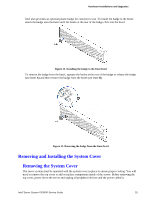
Hardware Installations and Upgrades Figure 40. Installing Processor - Install the Processor Note: The underside of the processor has components that may damage the socket pins if installed improperly. Processor must align correctly with the socket opening before installation. DO NOT DROP processor into socket! 4. Remove the Cover. Press the cover to remove it. Save the protective cover. Figure 41. Installing Processor - Remove the Cover 5. Close the Load Plate. Carefully lower the load plate over the processor. Figure 42. Installing Processor - Close the Load Plate 6. Latch the Locking Lever. Push down on the locking lever on the CLOSE 1st side (see letter A). Slide the tip of the lever under the notch in the load plate (see letter B). Make sure the load plate tab engages under the socket lever when fully closed. Repeat the steps to latch the locking lever on the other side (see letter C). Latch the levers in the order as shown. Figure 43. Installing Processor - Latch the Locking Lever 30 Intel® Server System R2000IP Service Guide
-
 1
1 -
2
-
3
-
4
-
5
-
6
-
7
-
8
-
9
-
10
-
11
-
12
-
13
-
14
-
15
-
16
-
17
-
18
-
19
-
20
-
21
-
22
-
23
-
24
-
25
-
26
-
27
-
28
-
29
-
30
-
31
-
32
-
33
-
34
-
35
-
36
-
 37
37 -
 38
38 -
 39
39 -
 40
40 -
 41
41 -
 42
42 -
 43
43 -
 44
44 -
 45
45 -
 46
46 -
 47
47 -
48
-
49
-
50
-
51
-
52
-
53
-
54
-
55
-
56
-
57
-
58
-
59
-
60
-
61
-
62
-
63
-
64
-
65
-
66
-
67
-
68
-
69
-
70
-
71
-
72
-
73
-
74
-
75
-
76
-
77
-
78
-
79
-
80
-
81
-
82
-
83
-
84
-
85
-
86
-
87
-
88
-
89
-
90
-
91
-
92
-
93
-
94
-
95
-
96
-
97
-
98
-
99
-
100
-
101
-
102
-
103
-
104
-
105
-
106
-
107
-
108
-
109
-
110
-
111
-
112
-
113
-
114
-
115
-
116
-
117
-
118
-
119
-
120
-
121
-
122
-
123
-
124
-
125
-
126
-
127
-
128
-
129
-
130
-
131
-
132
-
133
-
134
-
135
-
136
-
137
-
138
-
139
-
140
-
141
-
142
-
143
-
144
-
145
-
146
-
147
-
148
-
149
-
150
-
151
-
152
-
153
-
154
-
155
-
156
-
157
-
158
-
159
-
160
-
161
-
162
-
163
-
164
-
165
-
166
-
167
-
168
-
169
-
170
-
171
-
172
-
173
-
174
-
175
-
176
-
177
-
178
-
179
-
180
-
181
-
182
-
183
-
184
-
185
-
186
-
187
-
188
-
189
-
190
-
191
-
192
 |
 |
