Intel S2600IP Service Guide - Page 43
Installing Processor Heatsinks, Removing the Processor
 |
View all Intel S2600IP manuals
Add to My Manuals
Save this manual to your list of manuals |
Page 43 highlights
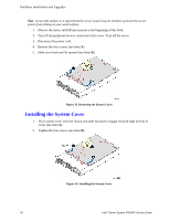
Hardware Installations and Upgrades Installing Processor Heatsink(s) 1. Remove the protective film on the TIM if present (see letter A). 2. Align heatsink fins to the front and back of the chassis for correct airflow. Airflow goes from front-to-back of chassis (see letter B). Each heatsink has four captive fasteners and should be tightened in a diagonal manner using the following procedure: 3. Using a #2 Phillips* screwdriver, start with screw 1 and engage screw threads by giving it two rotations and stop (see letter C). (Do not fully tighten.) 4. Proceed to screw 2 and engage screw threads by giving it two rotations and stop (see letter D). Similarly, engage screws 3 and 4. 5. Repeat steps C and D by giving each screw two rotations each time until each screw is lightly tightened up to a maximum of 8 inch-lbs torque (see letter E). Figure 44. Installing Processor Heatsink Removing the Processor 1. Remove the processor heatsink, see Figure 37 2. Open the socket lever, see Figure 38. 3. Open the load plate, see Figure 39. Intel® Server System R2000IP Service Guide 31
-
 1
1 -
2
-
3
-
4
-
5
-
6
-
7
-
8
-
9
-
10
-
11
-
12
-
13
-
14
-
15
-
16
-
17
-
18
-
19
-
20
-
21
-
22
-
23
-
24
-
25
-
26
-
27
-
28
-
29
-
30
-
31
-
32
-
33
-
34
-
35
-
36
-
37
-
 38
38 -
 39
39 -
 40
40 -
 41
41 -
 42
42 -
 43
43 -
 44
44 -
 45
45 -
 46
46 -
 47
47 -
 48
48 -
49
-
50
-
51
-
52
-
53
-
54
-
55
-
56
-
57
-
58
-
59
-
60
-
61
-
62
-
63
-
64
-
65
-
66
-
67
-
68
-
69
-
70
-
71
-
72
-
73
-
74
-
75
-
76
-
77
-
78
-
79
-
80
-
81
-
82
-
83
-
84
-
85
-
86
-
87
-
88
-
89
-
90
-
91
-
92
-
93
-
94
-
95
-
96
-
97
-
98
-
99
-
100
-
101
-
102
-
103
-
104
-
105
-
106
-
107
-
108
-
109
-
110
-
111
-
112
-
113
-
114
-
115
-
116
-
117
-
118
-
119
-
120
-
121
-
122
-
123
-
124
-
125
-
126
-
127
-
128
-
129
-
130
-
131
-
132
-
133
-
134
-
135
-
136
-
137
-
138
-
139
-
140
-
141
-
142
-
143
-
144
-
145
-
146
-
147
-
148
-
149
-
150
-
151
-
152
-
153
-
154
-
155
-
156
-
157
-
158
-
159
-
160
-
161
-
162
-
163
-
164
-
165
-
166
-
167
-
168
-
169
-
170
-
171
-
172
-
173
-
174
-
175
-
176
-
177
-
178
-
179
-
180
-
181
-
182
-
183
-
184
-
185
-
186
-
187
-
188
-
189
-
190
-
191
-
192
 |
 |
