Intel SBXL52 Hardware Maintenance Manual - Page 54
fully open position before you insert the microprocessor in the socket. Failure to do so might
 |
View all Intel SBXL52 manuals
Add to My Manuals
Save this manual to your list of manuals |
Page 54 highlights
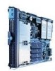
7. Remove the heat-sink filler. 8. Install the microprocessor: a. Remove the protective cover, tape, or label from the surface of the microprocessor socket, if one is present. b. Touch the static-protective package containing the new microprocessor to any unpainted metal surface on the SBCE chassis or any unpainted surface on any other grounded rack component; then, remove the microprocessor from the package. c. Rotate the locking lever on the microprocessor socket from its closed and locked position until it stops or clicks in the fully open position (approximately a 135° angle), as shown. Attention: You must ensure that the locking lever on the microprocessor socket is in the fully open position before you insert the microprocessor in the socket. Failure to do so might result in permanent damage to the microprocessor, microprocessor socket, and system board. Lever closed or Lever fully open Lever closed Lever fully open d. Center the microprocessor over the microprocessor socket. Align the triangle on the corner of the microprocessor with the triangle on the corner of the socket and carefully press the microprocessor into the socket. Attention: • Do not use excessive force when pressing the microprocessor into the socket. • Make sure that the microprocessor is oriented and aligned correctly in the socket before you try to close the lever. 40 SBXL52: Hardware Maintenance Manual and Troubleshooting Guide
-
 1
1 -
2
-
3
-
4
-
5
-
6
-
7
-
8
-
9
-
10
-
11
-
12
-
13
-
14
-
15
-
16
-
17
-
18
-
19
-
20
-
21
-
22
-
23
-
24
-
25
-
26
-
27
-
28
-
29
-
30
-
31
-
32
-
33
-
34
-
35
-
36
-
37
-
38
-
39
-
40
-
41
-
42
-
43
-
44
-
45
-
46
-
47
-
48
-
 49
49 -
 50
50 -
 51
51 -
 52
52 -
 53
53 -
 54
54 -
 55
55 -
 56
56 -
 57
57 -
 58
58 -
 59
59 -
60
-
61
-
62
-
63
-
64
-
65
-
66
-
67
-
68
-
69
-
70
-
71
-
72
-
73
-
74
-
75
-
76
-
77
-
78
-
79
-
80
-
81
-
82
-
83
-
84
-
85
-
86
-
87
-
88
-
89
-
90
-
91
-
92
-
93
-
94
-
95
-
96
-
97
-
98
-
99
-
100
-
101
-
102
-
103
-
104
-
105
-
106
-
107
-
108
-
109
-
110
-
111
-
112
-
113
-
114
-
115
-
116
-
117
-
118
-
119
-
120
-
121
-
122
-
123
-
124
-
125
-
126
 |
 |
