Intel SBXL52 Hardware Maintenance Manual - Page 77
Service replaceable units, Microprocessor removal
 |
View all Intel SBXL52 manuals
Add to My Manuals
Save this manual to your list of manuals |
Page 77 highlights
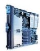
8 Service replaceable units This chapter describes the removal of server components. ✏ Important The field replaceable unit (FRU) procedures are intended for trained servicers who are familiar with Intel products. See the parts listing in "System" on page 104 to determine if the component being replaced is a customer replaceable unit (CRU) or a FRU. Microprocessor removal ✏ NOTE • Read "Installation guidelines" on page 27. • Read the safety notices at "Electrical Safety" on page vi. • Read "Handling electrostatic discharge-sensitive devices" on page vi Complete the following steps to remove a microprocessor: 1. Shut down the operating system, turn off the blade server, and remove the blade server from the SBCE unit (see "Removing the blade server from the SBCE unit" on page 33). 2. Carefully lay the blade server on a flat, non-conductive surface. 3. Open the blade server cover (see "Opening the blade server cover" on page 33 for instructions). 4. Remove the bezel assembly (see "Removing the blade server bezel assembly" on page 35 for instructions). 5. Identify the microprocessor to be removed. ✏ NOTE If you are replacing a failed microprocessor, verify that you have selected the correct microprocessor for replacement (see "Light path diagnostics" on page 81). 6. Remove the heat sink: a. Loosen one captive screw fully; then, loosen the other captive screw. Attention: Loosening one screw fully before loosening the other screw will help to break the thermal bond that adheres the heat sink to the microprocessor. b. Gently pull the heat sink off of the microprocessor. 7. Rotate the locking lever on the microprocessor socket from its closed and locked position until it stops or clicks in the fully open position (approximately 135° angle), as shown. Then, see the documentation provided with the microprocessor option for complete installation instructions. Attention: You must ensure that the locking lever on the microprocessor socket is in the fully open position before you insert the microprocessor in the socket. Failure to do so might result in permanent damage to the microprocessor, microprocessor socket, and system board. 63
-
 1
1 -
2
-
3
-
4
-
5
-
6
-
7
-
8
-
9
-
10
-
11
-
12
-
13
-
14
-
15
-
16
-
17
-
18
-
19
-
20
-
21
-
22
-
23
-
24
-
25
-
26
-
27
-
28
-
29
-
30
-
31
-
32
-
33
-
34
-
35
-
36
-
37
-
38
-
39
-
40
-
41
-
42
-
43
-
44
-
45
-
46
-
47
-
48
-
49
-
50
-
51
-
52
-
53
-
54
-
55
-
56
-
57
-
58
-
59
-
60
-
61
-
62
-
63
-
64
-
65
-
66
-
67
-
68
-
69
-
70
-
71
-
 72
72 -
 73
73 -
 74
74 -
 75
75 -
 76
76 -
 77
77 -
 78
78 -
 79
79 -
 80
80 -
 81
81 -
 82
82 -
83
-
84
-
85
-
86
-
87
-
88
-
89
-
90
-
91
-
92
-
93
-
94
-
95
-
96
-
97
-
98
-
99
-
100
-
101
-
102
-
103
-
104
-
105
-
106
-
107
-
108
-
109
-
110
-
111
-
112
-
113
-
114
-
115
-
116
-
117
-
118
-
119
-
120
-
121
-
122
-
123
-
124
-
125
-
126
 |
 |
