Intel SBXL52 Hardware Maintenance Manual - Page 68
Installing the blade server in the SBCE unit, Select the bay for the blade server.
 |
View all Intel SBXL52 manuals
Add to My Manuals
Save this manual to your list of manuals |
Page 68 highlights
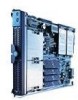
2. If you removed the blade bezel assembly, replace it now. See "Installing the blade server bezel assembly" on page 51 for instructions. 3. Lower the cover so that the slots at the rear slide down onto the pins at the rear of the blade server, as shown in the illustration. Before closing the cover, check that all components are installed and seated correctly and that you have not left loose tools or parts inside the blade server. 4. Pivot the cover to the closed position as shown in the illustration, until it clicks into place. Installing the blade server in the SBCE unit Complete the following steps to install a blade server in the SBCE unit. xxCAUTION: Hazardous energy is present when the blade server is connected to the power source. Always replace the blade cover before installing the blade server. 1. Review "Electrical Safety" on page vi and "Installation guidelines" on page 27 through "Handling static-sensitive devices" on page 27. 2. If you have not done so already, install any options needed, such as disk drives or memory, in the blade server. 3. Select the bay for the blade server. Notes: a. If the blade server has a SCSI storage expansion unit installed on it, the blade server and expansion option require two adjacent bays. b. When any blade server or option is in blade bays 7 through 14, power modules must be present in power bays 1 and 2, and power modules must be present in power bays 3 and 4. 54 SBXL52: Hardware Maintenance Manual and Troubleshooting Guide
-
 1
1 -
2
-
3
-
4
-
5
-
6
-
7
-
8
-
9
-
10
-
11
-
12
-
13
-
14
-
15
-
16
-
17
-
18
-
19
-
20
-
21
-
22
-
23
-
24
-
25
-
26
-
27
-
28
-
29
-
30
-
31
-
32
-
33
-
34
-
35
-
36
-
37
-
38
-
39
-
40
-
41
-
42
-
43
-
44
-
45
-
46
-
47
-
48
-
49
-
50
-
51
-
52
-
53
-
54
-
55
-
56
-
57
-
58
-
59
-
60
-
61
-
62
-
 63
63 -
 64
64 -
 65
65 -
 66
66 -
 67
67 -
 68
68 -
 69
69 -
 70
70 -
 71
71 -
 72
72 -
 73
73 -
74
-
75
-
76
-
77
-
78
-
79
-
80
-
81
-
82
-
83
-
84
-
85
-
86
-
87
-
88
-
89
-
90
-
91
-
92
-
93
-
94
-
95
-
96
-
97
-
98
-
99
-
100
-
101
-
102
-
103
-
104
-
105
-
106
-
107
-
108
-
109
-
110
-
111
-
112
-
113
-
114
-
115
-
116
-
117
-
118
-
119
-
120
-
121
-
122
-
123
-
124
-
125
-
126
 |
 |
