Intel SR1670HV Service Guide - Page 10

List of s - 1u

Page 10 highlights

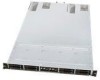
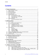
List of Figures List of Figures Figure 1. Server System Features 3 Figure 2. System Features - Back Panel 3 Figure 3. System Component Identification 4 Figure 4. Server Node Connectors and Components 5 Figure 5. Front Control Panel LEDs 6 Figure 6. RJ-45 Ports 1 and 2 LEDs 7 Figure 7. HDD Status LED...7 Figure 8. Cable Connections ...8 Figure 9. Rear Panel Thumbscrews 9 Figure 10. Sliding the Chassis Cover 9 Figure 11. LGA1366 Socket...10 Figure 12. Retention Tab and Load Lever 11 Figure 13. Load Plate...11 Figure 14. PnP Cap ...11 Figure 15. CPU Notch and Alignment Key 12 Figure 16. Applying Thermal Paste 12 Figure 17. Closing the Load Plate 13 Figure 18. Installing the Heatsink (Passive Heatsink Shown 14 Figure 19. Removing the Heatsink 15 Figure 20. DDR3 DIMM Sockets Location 16 Figure 21. Unlocked Retaining Clips 19 Figure 22. Locked Retaining Clips 19 Figure 23. DIMM Notch...19 Figure 24. Riser Card Bracket ...20 Figure 25. Removing the Screw from Slot Bay 20 Figure 26. PCI Express* x 16 Card 20 Figure 27. Pressing Rising Card Bracket for Golden Connectors to Fit 21 Figure 28. BMC_FW1 Header ...22 Figure 29. Orienting the Management Module Card 22 Figure 30. Server Management LAN Port 22 Figure 31. Hard Disk Drives...23 Figure 32. Releasing the Drive Tray 23 Figure 33. Placing a SATAII/SAS Hard Disk Drive on the Tray 23 Figure 34. Pushing the Tray Lever 24 Figure 35. Rackmount Rail Kit Items 25 Figure 36. Screw positions on the rail 25 Figure 37. Attaching the Front End of the Server Rail to Side of Chassis 26 Figure 38. Sliding the Server Rail 26 Figure 39. Securing the Server Rail With Screws 26 Figure 40. Positioning the Rack Rail to 1U Space on Rack 27 Figure 41. Mounting Ear ...27 Figure 42. Holding and Pressing the PSU Latch 28 Figure 43. Pulling Out the Failed PSU 28 Figure 44. Pushing the New PSU Into the Chassis 28 Figure 45. Disconnecting System Fan Cable 29 Figure 46. Lifting System Fan ...29 Figure 47. Inserting Fan Into the Fan Cage 29 x Intel® Server System SR1670HV Service Guide

  • 1
  • 2
  • 3
  • 4
  • 5
  • 6
  • 7
  • 8
  • 9
  • 10
  • 11
  • 12
  • 13
  • 14
  • 15
  • 16
  • 17
  • 18
  • 19
  • 20
  • 21
  • 22
  • 23
  • 24
  • 25
  • 26
  • 27
  • 28
  • 29
  • 30
  • 31
  • 32
  • 33
  • 34
  • 35
  • 36
  • 37
  • 38
  • 39
  • 40
  • 41
  • 42
  • 43
  • 44
  • 45
  • 46
  • 47
  • 48
  • 49
  • 50
  • 51
  • 52
  • 53
  • 54
  • 55
  • 56
  • 57
  • 58
  • 59
  • 60
  • 61
  • 62
  • 63
  • 64
  • 65
  • 66
  • 67
  • 68
  • 69
  • 70
  • 71
  • 72
  • 73
  • 74
  • 75
  • 76
  • 77
  • 78
  • 79
  • 80
  • 81
  • 82
  • 83
  • 84
  • 85
  • 86
  • 87
  • 88
  • 89
  • 90
  • 91
  • 92
  • 93
  • 94
  • 95
  • 96
  • 97
  • 98
  • 99
  • 100
  • 101
  • 102
  • 103
  • 104
  • 105
  • 106
  • 107
  • 108
  • 109
  • 110
  • 111
  • 112
  • 113
  • 114
  • 115
  • 116
  • 117
  • 118
  • 119
  • 120
  • 121
  • 122
  • 123
  • 124
  • 125
  • 126
  • 127
  • 128
  • 129
  • 130
  • 131
  • 132
  • 133
  • 134
  • 135
  • 136
  • 137
  • 138
  • 139
  • 140
  • 141
  • 142
  • 143
  • 144
  • 145
  • 146
  • 147
  • 148
  • 149
  • 150
  • 151
  • 152
  • 153
  • 154
  • 155
  • 156
  • 157

List of Figures
x
Intel
®
Server System SR1670HV Service Guide
List of Figures
Figure 1. Server System Features
................................................................................................
3
Figure 2. System Features – Back Panel
.....................................................................................
3
Figure 3. System Component Identification
..................................................................................
4
Figure 4. Server Node Connectors and Components
...................................................................
5
Figure 5. Front Control Panel LEDs
..............................................................................................
6
Figure 6. RJ-45 Ports 1 and 2 LEDs
.............................................................................................
7
Figure 7. HDD Status LED
............................................................................................................
7
Figure 8. Cable Connections
........................................................................................................
8
Figure 9. Rear Panel Thumbscrews
.............................................................................................
9
Figure 10. Sliding the Chassis Cover
............................................................................................
9
Figure 11. LGA1366 Socket
........................................................................................................
10
Figure 12. Retention Tab and Load Lever
..................................................................................
11
Figure 13. Load Plate
..................................................................................................................
11
Figure 14. PnP Cap
....................................................................................................................
11
Figure 15. CPU Notch and Alignment Key
..................................................................................
12
Figure 16. Applying Thermal Paste
.............................................................................................
12
Figure 17. Closing the Load Plate
...............................................................................................
13
Figure 18. Installing the Heatsink (Passive Heatsink Shown)
.....................................................
14
Figure 19. Removing the Heatsink
..............................................................................................
15
Figure 20. DDR3 DIMM Sockets Location
..................................................................................
16
Figure 21. Unlocked Retaining Clips
...........................................................................................
19
Figure 22. Locked Retaining Clips
..............................................................................................
19
Figure 23. DIMM Notch
...............................................................................................................
19
Figure 24. Riser Card Bracket
....................................................................................................
20
Figure 25. Removing the Screw from Slot Bay
...........................................................................
20
Figure 26. PCI Express* x 16 Card
.............................................................................................
20
Figure 27. Pressing Rising Card Bracket for Golden Connectors to Fit
......................................
21
Figure 28. BMC_FW1 Header
....................................................................................................
22
Figure 29. Orienting the Management Module Card
...................................................................
22
Figure 30. Server Management LAN Port
...................................................................................
22
Figure 31. Hard Disk Drives
........................................................................................................
23
Figure 32. Releasing the Drive Tray
...........................................................................................
23
Figure 33. Placing a SATAII/SAS Hard Disk Drive on the Tray
..................................................
23
Figure 34. Pushing the Tray Lever
..............................................................................................
24
Figure 35. Rackmount Rail Kit Items
..........................................................................................
25
Figure 36. Screw positions on the rail
.........................................................................................
25
Figure 37. Attaching the Front End of the Server Rail to Side of Chassis
..................................
26
Figure 38. Sliding the Server Rail
...............................................................................................
26
Figure 39. Securing the Server Rail With Screws
.......................................................................
26
Figure 40. Positioning the Rack Rail to 1U Space on Rack
........................................................
27
Figure 41. Mounting Ear
.............................................................................................................
27
Figure 42. Holding and Pressing the PSU Latch
........................................................................
28
Figure 43. Pulling Out the Failed PSU
........................................................................................
28
Figure 44. Pushing the New PSU Into the Chassis
....................................................................
28
Figure 45. Disconnecting System Fan Cable
..............................................................................
29
Figure 46. Lifting System Fan
.....................................................................................................
29
Figure 47. Inserting Fan Into the Fan Cage
................................................................................
29