Intel SR1670HV Service Guide - Page 48
Front Control Panel Replacement
 |
UPC - 735858210034
View all Intel SR1670HV manuals
Add to My Manuals
Save this manual to your list of manuals |
Page 48 highlights
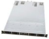
System Service Figure 55. Aligning the Module with the Alignment Slots on the Chassis 17. Slide the hard drive bay module back until the screw holes are aligned. 18. Secure the HDD bay module to the chassis using the six screws, three on each side. 19. Install the hard drives into the same position from which they were removed. 4.4 Front Control Panel Replacement The system includes two separate control panels (one for each server node) on the front of the chassis which are mounted onto a single removable module. In the event a control panel's features stop functioning and it is determined it should be replaced with a spare, you must perform the following procedure. 1. Power down both server modules and remove AC power. 2. Remove the single screw holding the Control Panel Module in place. Figure 56. Control Panel Module Screw 3. Carefully pull back the Control Panel module until the cables are fully exposed and accessible. Intel® Server System SR1670HV Service Guide 33
-
 1
1 -
2
-
3
-
4
-
5
-
6
-
7
-
8
-
9
-
10
-
11
-
12
-
13
-
14
-
15
-
16
-
17
-
18
-
19
-
20
-
21
-
22
-
23
-
24
-
25
-
26
-
27
-
28
-
29
-
30
-
31
-
32
-
33
-
34
-
35
-
36
-
37
-
38
-
39
-
40
-
41
-
42
-
 43
43 -
 44
44 -
 45
45 -
 46
46 -
 47
47 -
 48
48 -
 49
49 -
 50
50 -
 51
51 -
 52
52 -
 53
53 -
54
-
55
-
56
-
57
-
58
-
59
-
60
-
61
-
62
-
63
-
64
-
65
-
66
-
67
-
68
-
69
-
70
-
71
-
72
-
73
-
74
-
75
-
76
-
77
-
78
-
79
-
80
-
81
-
82
-
83
-
84
-
85
-
86
-
87
-
88
-
89
-
90
-
91
-
92
-
93
-
94
-
95
-
96
-
97
-
98
-
99
-
100
-
101
-
102
-
103
-
104
-
105
-
106
-
107
-
108
-
109
-
110
-
111
-
112
-
113
-
114
-
115
-
116
-
117
-
118
-
119
-
120
-
121
-
122
-
123
-
124
-
125
-
126
-
127
-
128
-
129
-
130
-
131
-
132
-
133
-
134
-
135
-
136
-
137
-
138
-
139
-
140
-
141
-
142
-
143
-
144
-
145
-
146
-
147
-
148
-
149
-
150
-
151
-
152
-
153
-
154
-
155
-
156
-
157
 |
 |
