Intel SR1670HV Service Guide - Page 6

Contents - memory

Page 6 highlights

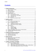
Contents Contents 1. Product Introduction 1 1.1 System Package Contents 1 1.2 System Features ...1 1.3 Front Panel Features ...2 1.4 Rear Panel Features ...3 1.5 Internal Features ...3 1.6 System LED Information 6 1.6.1 Front Control Panel LEDs 6 1.6.2 RJ-45 LAN Ports 1 and 2 LEDs 7 1.6.3 HDD Status LED 7 1.7 Cable Connections...7 1.7.1 Pre-Connected System Cables 8 2. Hardware Setup 9 2.1 Chassis Cover...9 2.1.1 Removing the Chassis Cover 9 2.2 Central Processing Unit (CPU 9 2.2.1 Installing the Processor 10 2.2.2 Installing the Processor Heatsink 13 2.2.3 Removing the Processor Heatsink 14 2.3 System Memory ...15 2.3.1 Overview...15 2.3.2 Memory Support 16 2.3.3 Installing a DIMM 18 2.3.4 Removing a DIMM 19 2.4 Installing a PCI Express* Add-In Card to the Riser Bracket 20 2.5 Installing the BMC Management Module 22 2.6 Hard Disk Drives ...23 3. Installing the Rackmount Rail Kit 25 3.1 Attaching the Rails to the Server 25 3.2 Attaching the Rack Rails 26 3.3 Rackmounting the Server 27 4. System Service 28 4.1 Replacing Power Supply Units (PSUs 28 4.2 Replacing System Fans 29 4.3 SATA/SAS BackPlane Replacement 30 4.4 Front Control Panel Replacement 33 5. Jumpers, Connectors, and LEDs 35 5.1 Configuration and Support Jumpers 35 5.1.1 5.1.2 5.1.3 5.1.4 Clear RTC RAM (CLRTC1 35 VGA Controller Setting (3-pin VGA_SW1 36 DDR3 Voltage Control Setting (4-pin LVDDR3_SEL1, LVDDR3_SEL2) ...... 36 LAN Controller Setting (3-poin LAN_SW1, LAN_SW2 37 vi Intel® Server System SR1670HV Service Guide

  • 1
  • 2
  • 3
  • 4
  • 5
  • 6
  • 7
  • 8
  • 9
  • 10
  • 11
  • 12
  • 13
  • 14
  • 15
  • 16
  • 17
  • 18
  • 19
  • 20
  • 21
  • 22
  • 23
  • 24
  • 25
  • 26
  • 27
  • 28
  • 29
  • 30
  • 31
  • 32
  • 33
  • 34
  • 35
  • 36
  • 37
  • 38
  • 39
  • 40
  • 41
  • 42
  • 43
  • 44
  • 45
  • 46
  • 47
  • 48
  • 49
  • 50
  • 51
  • 52
  • 53
  • 54
  • 55
  • 56
  • 57
  • 58
  • 59
  • 60
  • 61
  • 62
  • 63
  • 64
  • 65
  • 66
  • 67
  • 68
  • 69
  • 70
  • 71
  • 72
  • 73
  • 74
  • 75
  • 76
  • 77
  • 78
  • 79
  • 80
  • 81
  • 82
  • 83
  • 84
  • 85
  • 86
  • 87
  • 88
  • 89
  • 90
  • 91
  • 92
  • 93
  • 94
  • 95
  • 96
  • 97
  • 98
  • 99
  • 100
  • 101
  • 102
  • 103
  • 104
  • 105
  • 106
  • 107
  • 108
  • 109
  • 110
  • 111
  • 112
  • 113
  • 114
  • 115
  • 116
  • 117
  • 118
  • 119
  • 120
  • 121
  • 122
  • 123
  • 124
  • 125
  • 126
  • 127
  • 128
  • 129
  • 130
  • 131
  • 132
  • 133
  • 134
  • 135
  • 136
  • 137
  • 138
  • 139
  • 140
  • 141
  • 142
  • 143
  • 144
  • 145
  • 146
  • 147
  • 148
  • 149
  • 150
  • 151
  • 152
  • 153
  • 154
  • 155
  • 156
  • 157

Contents
vi
Intel
®
Server System SR1670HV Service Guide
Contents
1.
Product Introduction
......................................................................................
1
1.1
System Package Contents
.............................................................................................
1
1.2
System Features
............................................................................................................
1
1.3
Front Panel Features
.....................................................................................................
2
1.4
Rear Panel Features
......................................................................................................
3
1.5
Internal Features
............................................................................................................
3
1.6
System LED Information
................................................................................................
6
1.6.1
Front Control Panel LEDs
................................................................................
6
1.6.2
RJ-45 LAN Ports 1 and 2 LEDs
.......................................................................
7
1.6.3
HDD Status LED
..............................................................................................
7
1.7
Cable Connections
.........................................................................................................
7
1.7.1
Pre-Connected System Cables
.......................................................................
8
2.
Hardware Setup
..............................................................................................
9
2.1
Chassis Cover
................................................................................................................
9
2.1.1
Removing the Chassis Cover
..........................................................................
9
2.2
Central Processing Unit (CPU)
......................................................................................
9
2.2.1
Installing the Processor
.................................................................................
10
2.2.2
Installing the Processor Heatsink
..................................................................
13
2.2.3
Removing the Processor Heatsink
................................................................
14
2.3
System Memory
...........................................................................................................
15
2.3.1
Overview
........................................................................................................
15
2.3.2
Memory Support
............................................................................................
16
2.3.3
Installing a DIMM
...........................................................................................
18
2.3.4
Removing a DIMM
.........................................................................................
19
2.4
Installing a PCI Express* Add-In Card to the Riser Bracket
.........................................
20
2.5
Installing the BMC Management Module
.....................................................................
22
2.6
Hard Disk Drives
..........................................................................................................
23
3.
Installing the Rackmount Rail Kit
...............................................................
25
3.1
Attaching the Rails to the Server
..................................................................................
25
3.2
Attaching the Rack Rails
..............................................................................................
26
3.3
Rackmounting the Server
.............................................................................................
27
4.
System Service
.............................................................................................
28
4.1
Replacing Power Supply Units (PSUs)
........................................................................
28
4.2
Replacing System Fans
...............................................................................................
29
4.3
SATA/SAS BackPlane Replacement
...........................................................................
30
4.4
Front Control Panel Replacement
................................................................................
33
5.
Jumpers, Connectors, and LEDs
................................................................
35
5.1
Configuration and Support Jumpers
............................................................................
35
5.1.1
Clear RTC RAM (CLRTC1)
...........................................................................
35
5.1.2
VGA Controller Setting (3-pin VGA_SW1)
....................................................
36
5.1.3
DDR3 Voltage Control Setting (4-pin LVDDR3_SEL1, LVDDR3_SEL2)
......
36
5.1.4
LAN Controller Setting (3-poin LAN_SW1, LAN_SW2)
.................................
37