Intel SR1670HV Service Guide - Page 47
Cable Bundles in the Hard Disk Drive Bay Module, SATA Cable Connection Order
 |
UPC - 735858210034
View all Intel SR1670HV manuals
Add to My Manuals
Save this manual to your list of manuals |
Page 47 highlights
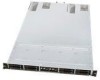
System Service 13. Carefully reposition the backplane over the guide pins on each side of the hard drive bay. Verify that all of the front panel cables are located completely within the open area behind the backplane. 14. Securely fasten all 12 screws into the backplane. Be careful not to overtighten them. 15. Reposition the hard drive bay module over the system fan assembly and reconnect all cables to the backplane. Reposition cable bundles within plastic cable holders. Figure 53. Cable Bundles in the Hard Disk Drive Bay Module NOTE: You must reconnect the SATA cables in the following order with the drive bay module still positioned in an upside down manner on top of the system fan assembly as shown SATA 1 SATA 2 SATA 4 SATA 3 Figure 54. SATA Cable Connection Order 16. Carefully reposition the hard drive bay module on to the server chassis, such that the module falls within alignment slots on each side of the chassis. 32 Intel® Server System SR1670HV Service Guide
-
 1
1 -
2
-
3
-
4
-
5
-
6
-
7
-
8
-
9
-
10
-
11
-
12
-
13
-
14
-
15
-
16
-
17
-
18
-
19
-
20
-
21
-
22
-
23
-
24
-
25
-
26
-
27
-
28
-
29
-
30
-
31
-
32
-
33
-
34
-
35
-
36
-
37
-
38
-
39
-
40
-
41
-
 42
42 -
 43
43 -
 44
44 -
 45
45 -
 46
46 -
 47
47 -
 48
48 -
 49
49 -
 50
50 -
 51
51 -
 52
52 -
53
-
54
-
55
-
56
-
57
-
58
-
59
-
60
-
61
-
62
-
63
-
64
-
65
-
66
-
67
-
68
-
69
-
70
-
71
-
72
-
73
-
74
-
75
-
76
-
77
-
78
-
79
-
80
-
81
-
82
-
83
-
84
-
85
-
86
-
87
-
88
-
89
-
90
-
91
-
92
-
93
-
94
-
95
-
96
-
97
-
98
-
99
-
100
-
101
-
102
-
103
-
104
-
105
-
106
-
107
-
108
-
109
-
110
-
111
-
112
-
113
-
114
-
115
-
116
-
117
-
118
-
119
-
120
-
121
-
122
-
123
-
124
-
125
-
126
-
127
-
128
-
129
-
130
-
131
-
132
-
133
-
134
-
135
-
136
-
137
-
138
-
139
-
140
-
141
-
142
-
143
-
144
-
145
-
146
-
147
-
148
-
149
-
150
-
151
-
152
-
153
-
154
-
155
-
156
-
157
 |
 |
