Konica Minolta C250i bizhub C360i/C300i/C250i Security Operations User Manual - Page 104
FAX function
 |
View all Konica Minolta C250i manuals
Add to My Manuals
Save this manual to your list of manuals |
Page 104 highlights
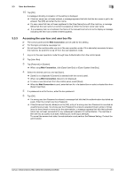
Appendix 2. FAX function (14) Take a sample copy, and confirm the image. If image troubles occur, first turn OFF and ON the main power switch, and then redo the steps from "Date & Time Setting/Time Zone Setting" to "Unit change". 2. FAX function 2.1 Installing/setting procedure of the FAX kit 2.1.1 Install procedure 1. Turn OFF the power switch and unplug the power cord from the power outlet. 2. Open the rear right cover. 3. Remove the connector cover at the lower portion inside the cover. 4. Remove the shield cover (FAX1) from the lower under side, inside the door. When installing a second fax kit, remove the shield cover (FAX2) from the upper side. 5. Make sure that the fax kit switch keys are placed in [Line 1]. When installing a second fax kit, flip the fax kit switch keys into [Line 2]. 6. Insert the fax kit into the under socket (FAX1) and secure it with the screws removed in step (4). Be careful not to pinch the harness between plates. When installing a second fax kit, insert the FAX kit into the upper socket (FAX2). When installing a second fax kit, insert the supplied modular cover into the modular jack (TEL) for Line 2. 7. Connect each of the two connectors of the fax kit to the corresponding port of FAX1. When installing a second fax kit, connect the two connectors to respective ports of FAX2. 8. Route the fax kit harness and the USB cable. 9. Reinstall the connector cover that has been removed in step (3). Fit the connector cover protrusion in the portion of the machine. Be careful not to pinch the harness. 2.1.2 Routing of the modular cable A. When the ferrite core is not installed to the supplied modular cable 1. Insert the supplied modular cable in the modular jack (LINE). If the user is connected with a key telephone system or a private branch exchange (PBX), do not connect the modular cable to where other than an analog line. 2. Insert the modular cable of the telephone line to the modular jack (TEL) of the fax kit (Line 1). 3. Insert the supplied modular cable in the modular jack (LINE). If the user is connected with a key telephone system or a private branch exchange (PBX), do not connect the modular cable to where other than an analog line. 4. Place the modular cable in the harness guide. 5. Pass the modular cable into the hole in the lower portion of the rear right cover. a) Remove the rear right cover from the paper feed cabinet or the desk. b) Remove the knockout from the rear right cover using nippers. c) Route the modular cable through the three wire saddles. d) Route the cable through the notch and attach the rear right cover. B. When the ferrite core is installed to the supplied modular cable 3
-
 1
1 -
2
-
3
-
4
-
5
-
6
-
7
-
8
-
9
-
10
-
11
-
12
-
13
-
14
-
15
-
16
-
17
-
18
-
19
-
20
-
21
-
22
-
23
-
24
-
25
-
26
-
27
-
28
-
29
-
30
-
31
-
32
-
33
-
34
-
35
-
36
-
37
-
38
-
39
-
40
-
41
-
42
-
43
-
44
-
45
-
46
-
47
-
48
-
49
-
50
-
51
-
52
-
53
-
54
-
55
-
56
-
57
-
58
-
59
-
60
-
61
-
62
-
63
-
64
-
65
-
66
-
67
-
68
-
69
-
70
-
71
-
72
-
73
-
74
-
75
-
76
-
77
-
78
-
79
-
80
-
81
-
82
-
83
-
84
-
85
-
86
-
87
-
88
-
89
-
90
-
91
-
92
-
93
-
94
-
95
-
96
-
97
-
98
-
 99
99 -
 100
100 -
 101
101 -
 102
102 -
 103
103 -
 104
104 -
 105
105 -
 106
106
 |
 |