Lantronix PremierWave XC PremierWave XC - User Guide - Page 22
Side Panel, USB 1, Fault, GSM Signal Strength, Relay Output, Inputs, Antenna
 |
View all Lantronix PremierWave XC manuals
Add to My Manuals
Save this manual to your list of manuals |
Page 22 highlights
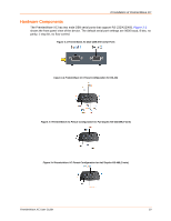
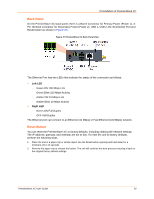
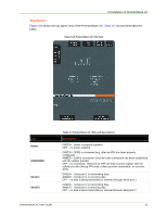
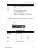
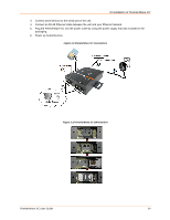
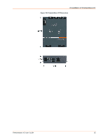
3:Installation of PremierWave XC LED USB 1 USB 2 Fault GSM Signal Strength Description GREEN - a USB device is connected to USB 1 Host port and is functioning properly OFF- no USB device is connected to USB 1 Host port GREEN - a USB device is connected to USB 2 Host port and is functioning properly OFF- no USB device is connected to USB 2 Host port RED- blinking when Events or Errors occurred OFF - system functioning normally GREEN - 3 to 5 LEDs lighted. Good to Strong signal strength AMBER/GREEN - 1 to 2 bi-colored LEDs lighted. Weak signal strength Side Panel On the PremierWave XC side panel, there is a 6-pin Terminal Connector for Relay and I/Os as well as an SMA Antenna Connector as shown in Figure 3-7. Figure 3-7 PremierWave XC Side View Connector Relay Output Inputs Antenna Table 3-2 PremierWave XC Side View Description Outputs Support 1A 24V Inputs accept voltage 0 to 30 VDC Max ON Min Max OFF Min Connect the provided SMA Antenna 30 VDC 2 VDC 0.7 VDC 0 VDC PremierWave XC User Guide 22
-
 1
1 -
2
-
3
-
4
-
5
-
6
-
7
-
8
-
9
-
10
-
11
-
12
-
13
-
14
-
15
-
16
-
 17
17 -
 18
18 -
 19
19 -
 20
20 -
 21
21 -
 22
22 -
 23
23 -
 24
24 -
 25
25 -
 26
26 -
 27
27 -
28
-
29
-
30
-
31
-
32
-
33
-
34
-
35
-
36
-
37
-
38
-
39
-
40
-
41
-
42
-
43
-
44
-
45
-
46
-
47
-
48
-
49
-
50
-
51
-
52
-
53
-
54
-
55
-
56
-
57
-
58
-
59
-
60
-
61
-
62
-
63
-
64
-
65
-
66
-
67
-
68
-
69
-
70
-
71
-
72
-
73
-
74
-
75
-
76
-
77
-
78
-
79
-
80
-
81
-
82
-
83
-
84
-
85
-
86
-
87
-
88
-
89
-
90
-
91
-
92
-
93
-
94
-
95
-
96
-
97
-
98
-
99
-
100
-
101
-
102
-
103
-
104
-
105
-
106
-
107
-
108
-
109
 |
 |
