Lantronix PremierWave XC PremierWave XC - User Guide - Page 23
Bottom Panel, Installing the PremierWave XC
 |
View all Lantronix PremierWave XC manuals
Add to My Manuals
Save this manual to your list of manuals |
Page 23 highlights
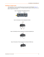
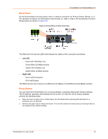
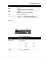
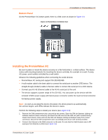
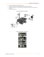
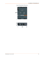
3:Installation of PremierWave XC Bottom Panel On the PremierWave XC bottom panel, there is a SIM cover as shown in Figure 3-8. Figure 3-8 PremierWave XC Bottom View Installing the PremierWave XC Be sure to place or mount the device securely on a flat horizontal or vertical surface. The device comes with mounting brackets for mounting the device vertically, for example on a wall. If using AC power, avoid outlets controlled by a wall switch. Observe the following guidelines when connecting the serial devices: PremierWave XC serial ports support RS-232/422/485 A null modem cable is the best cable to connect the serial port to another DTE device. The straight-though (modem) cable is the best cable to connect the serial port to a DCE device. Connect your RJ-45 Ethernet cable to the RJ-45 serial port of the unit The device supports a power range of 9 to 30 VDC. You can power up the device with the included 12VDC power supply with barrel-power connector and/or the 3-pin terminal connector for backup power supply. Note: As soon as you plug the device into power, the device powers up automatically, the self-test begins, and LEDs indicate the device's status. Perform the following steps to install your device (see Figure 3-9): 1. Remove the SIM compartment door, secured by two screws. Open the SIM slot fastener (sliding top fastener towards Power connector) and Insert the SIM card into the SIM slot (with contacts facing toward main board). Close and lock the SIM slot fastener (sliding top fastener away from Power connector). Secure the SIM compartment door accordingly and secure with screws provided. 2. Connect the Antenna to the SMA connector on the side. Do note that the Safe Distance due to RF exposure from Antenna is 23cm (see Figure 3-9). PremierWave XC User Guide 23
-
 1
1 -
2
-
3
-
4
-
5
-
6
-
7
-
8
-
9
-
10
-
11
-
12
-
13
-
14
-
15
-
16
-
17
-
 18
18 -
 19
19 -
 20
20 -
 21
21 -
 22
22 -
 23
23 -
 24
24 -
 25
25 -
 26
26 -
 27
27 -
 28
28 -
29
-
30
-
31
-
32
-
33
-
34
-
35
-
36
-
37
-
38
-
39
-
40
-
41
-
42
-
43
-
44
-
45
-
46
-
47
-
48
-
49
-
50
-
51
-
52
-
53
-
54
-
55
-
56
-
57
-
58
-
59
-
60
-
61
-
62
-
63
-
64
-
65
-
66
-
67
-
68
-
69
-
70
-
71
-
72
-
73
-
74
-
75
-
76
-
77
-
78
-
79
-
80
-
81
-
82
-
83
-
84
-
85
-
86
-
87
-
88
-
89
-
90
-
91
-
92
-
93
-
94
-
95
-
96
-
97
-
98
-
99
-
100
-
101
-
102
-
103
-
104
-
105
-
106
-
107
-
108
-
109
 |
 |
