Lenovo ThinkServer RD240 Hardware Maintenance Manual - Page 137
Starting the Configuration Utility program, displayed at the bottom of each screen.
 |
View all Lenovo ThinkServer RD240 manuals
Add to My Manuals
Save this manual to your list of manuals |
Page 137 highlights
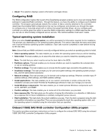
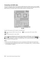
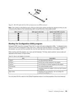
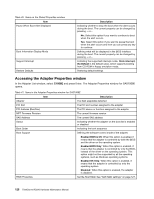
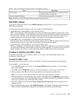
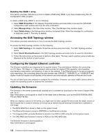
Figure 67. Mini SAS cable with four SAS connectors and one SGPIO connector Note: The number on the label for each of the four SAS signal cables indicates the sequence when you are connecting the cables to the corresponding SAS connectors (0-3) on the system board. SAS connector 6 7 8 9 SAS signal cable label P1 P2 P3 P4 System board SAS connector SAS connector 0 SAS connector 1 SAS connector 2 SAS connector 3 Starting the Configuration Utility program During the POST, when the message "Press Ctrl-C to start LSI Logic configuration Utility..." is displayed, press Ctrl+C to enter the Configuration Utility main menu. Press Enter and the Adapter List window is displayed. In this window, you can view the controller list, view the hard disk drive information, and configure RAID. When working with this program, you must use the keyboard. The keys used to perform various tasks are displayed at the bottom of each screen. Table 39. Items in the Adapter List window Item Adapter PCI Bus Dev/Fnc FW Revision Status Boot Order Description The SAS adapter(s) detected The PCI bus number assigned to the adapter The PCI device or function assigned to the adapter The current firmware version Indicating whether the adapter on the boot list is enabled or disabled Indicating the boot sequence. You can change the sequence by pressing + or -. You can press Alt+N to switch to the Global Properties window to set the properties of boot and interrupt. Chapter 9. Configuring the server 125
-
 1
1 -
2
-
3
-
4
-
5
-
6
-
7
-
8
-
9
-
10
-
11
-
12
-
13
-
14
-
15
-
16
-
17
-
18
-
19
-
20
-
21
-
22
-
23
-
24
-
25
-
26
-
27
-
28
-
29
-
30
-
31
-
32
-
33
-
34
-
35
-
36
-
37
-
38
-
39
-
40
-
41
-
42
-
43
-
44
-
45
-
46
-
47
-
48
-
49
-
50
-
51
-
52
-
53
-
54
-
55
-
56
-
57
-
58
-
59
-
60
-
61
-
62
-
63
-
64
-
65
-
66
-
67
-
68
-
69
-
70
-
71
-
72
-
73
-
74
-
75
-
76
-
77
-
78
-
79
-
80
-
81
-
82
-
83
-
84
-
85
-
86
-
87
-
88
-
89
-
90
-
91
-
92
-
93
-
94
-
95
-
96
-
97
-
98
-
99
-
100
-
101
-
102
-
103
-
104
-
105
-
106
-
107
-
108
-
109
-
110
-
111
-
112
-
113
-
114
-
115
-
116
-
117
-
118
-
119
-
120
-
121
-
122
-
123
-
124
-
125
-
126
-
127
-
128
-
129
-
130
-
131
-
 132
132 -
 133
133 -
 134
134 -
 135
135 -
 136
136 -
 137
137 -
 138
138 -
 139
139 -
 140
140 -
 141
141 -
 142
142 -
143
-
144
-
145
-
146
-
147
-
148
-
149
-
150
-
151
-
152
-
153
-
154
-
155
-
156
-
157
-
158
-
159
-
160
-
161
-
162
-
163
-
164
-
165
-
166
 |
 |
