Lenovo ThinkServer RD240 Hardware Maintenance Manual - Page 44
The following table introduces the jumper switches on the system board.
 |
View all Lenovo ThinkServer RD240 manuals
Add to My Manuals
Save this manual to your list of manuals |
Page 44 highlights
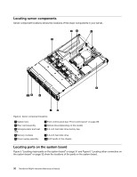
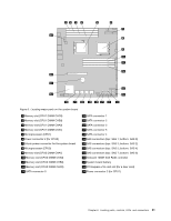
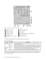
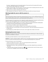
Figure 6. Locating other connectors on the system board 1 System fan 1 connector 2 System fan 2 connector 3 System fan 3 connector 4 System fan 4 connector 5 Front USB connector 6 J51 (SGPIO connector for onboard SAS port 1-4) 7 J35 (for front control cable) 8 JP1 (clear CMOS) 9 USB 2 connector 10 J21 (SGPIO connector for onboard SAS port 5-8) 11 JP7 (set onboard SAS) 12 J16 (COM2 connector) The following table introduces the jumper switches on the system board. Table 7. Jumper settings Jumper Position JP1: Clear Pins 1-2 CMOS Pins 2-3 JP7: Set Onboard SAS Pins 1-2 Pins 2-3 Description The default position at which the jumper is placed on pins 1-2 during the normal operation of the system. If the jumper is placed on pins 2-3, when the jumper is moved back to the default positions and at the next startup, the settings of CMOS will be cleared automatically. The default position at which the jumper is placed on pins 1-2 during the normal operation of the system. The onboard SAS controller is Enabled. If the jumper is placed on pins 2-3, the onboard SAS controller is Disabled. Note: Before clearing the CMOS, turn off the server and disconnect the power cord. Move the jumper from pins 1-2 to pins 2-3. Wait more than five minutes and then move the jumper back to the normal position (pins 1-2) to clear CMOS. 32 ThinkServer RD240 Hardware Maintenance Manual
-
 1
1 -
2
-
3
-
4
-
5
-
6
-
7
-
8
-
9
-
10
-
11
-
12
-
13
-
14
-
15
-
16
-
17
-
18
-
19
-
20
-
21
-
22
-
23
-
24
-
25
-
26
-
27
-
28
-
29
-
30
-
31
-
32
-
33
-
34
-
35
-
36
-
37
-
38
-
 39
39 -
 40
40 -
 41
41 -
 42
42 -
 43
43 -
 44
44 -
 45
45 -
 46
46 -
 47
47 -
 48
48 -
 49
49 -
50
-
51
-
52
-
53
-
54
-
55
-
56
-
57
-
58
-
59
-
60
-
61
-
62
-
63
-
64
-
65
-
66
-
67
-
68
-
69
-
70
-
71
-
72
-
73
-
74
-
75
-
76
-
77
-
78
-
79
-
80
-
81
-
82
-
83
-
84
-
85
-
86
-
87
-
88
-
89
-
90
-
91
-
92
-
93
-
94
-
95
-
96
-
97
-
98
-
99
-
100
-
101
-
102
-
103
-
104
-
105
-
106
-
107
-
108
-
109
-
110
-
111
-
112
-
113
-
114
-
115
-
116
-
117
-
118
-
119
-
120
-
121
-
122
-
123
-
124
-
125
-
126
-
127
-
128
-
129
-
130
-
131
-
132
-
133
-
134
-
135
-
136
-
137
-
138
-
139
-
140
-
141
-
142
-
143
-
144
-
145
-
146
-
147
-
148
-
149
-
150
-
151
-
152
-
153
-
154
-
155
-
156
-
157
-
158
-
159
-
160
-
161
-
162
-
163
-
164
-
165
-
166
 |
 |
