Lenovo ThinkServer RD240 Hardware Maintenance Manual - Page 43
Memory slot CPU0 DIMM CHA1
 |
View all Lenovo ThinkServer RD240 manuals
Add to My Manuals
Save this manual to your list of manuals |
Page 43 highlights
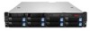
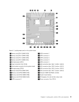
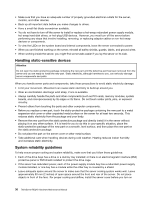
Figure 5. Locating major parts on the system board 1 Memory slot (CPU1 DIMM CHC0) 2 Memory slot (CPU1 DIMM CHB0) 3 Memory slot (CPU1 DIMM CHA0) 4 Memory slot (CPU1 DIMM CHA1) 5 Microprocessor (CPU1) 6 Power connector 2 (for CPU0) 7 24-pin power connector for the system board 8 Microprocessor (CPU0) 9 Memory slot (CPU0 DIMM CHA1) 10 Memory slot (CPU0 DIMM CHA0) 11 Memory slot (CPU0 DIMM CHB0) 12 Memory slot (CPU0 DIMM CHC0) 13 SATA connector 0 14 SATA connector 1 15 SATA connector 2 16 SATA connector 3 17 SATA connector 5 18 SATA connector 4 19 SAS connectors (top: SAS 1; bottom: SAS 0) 20 SAS connectors (top: SAS 3; bottom: SAS 2) 21 SAS connectors (top: SAS 5; bottom: SAS 4) 22 SAS connectors (top: SAS 7; bottom: SAS 6) 23 Onboard 1068E SAS RAID controller 24 System board battery 25 PCI Express x16 card slot (for a riser card) 26 Power connector 3 (for CPU1) Chapter 6. Locating parts, controls, LEDs, and connectors 31
-
 1
1 -
2
-
3
-
4
-
5
-
6
-
7
-
8
-
9
-
10
-
11
-
12
-
13
-
14
-
15
-
16
-
17
-
18
-
19
-
20
-
21
-
22
-
23
-
24
-
25
-
26
-
27
-
28
-
29
-
30
-
31
-
32
-
33
-
34
-
35
-
36
-
37
-
 38
38 -
 39
39 -
 40
40 -
 41
41 -
 42
42 -
 43
43 -
 44
44 -
 45
45 -
 46
46 -
 47
47 -
 48
48 -
49
-
50
-
51
-
52
-
53
-
54
-
55
-
56
-
57
-
58
-
59
-
60
-
61
-
62
-
63
-
64
-
65
-
66
-
67
-
68
-
69
-
70
-
71
-
72
-
73
-
74
-
75
-
76
-
77
-
78
-
79
-
80
-
81
-
82
-
83
-
84
-
85
-
86
-
87
-
88
-
89
-
90
-
91
-
92
-
93
-
94
-
95
-
96
-
97
-
98
-
99
-
100
-
101
-
102
-
103
-
104
-
105
-
106
-
107
-
108
-
109
-
110
-
111
-
112
-
113
-
114
-
115
-
116
-
117
-
118
-
119
-
120
-
121
-
122
-
123
-
124
-
125
-
126
-
127
-
128
-
129
-
130
-
131
-
132
-
133
-
134
-
135
-
136
-
137
-
138
-
139
-
140
-
141
-
142
-
143
-
144
-
145
-
146
-
147
-
148
-
149
-
150
-
151
-
152
-
153
-
154
-
155
-
156
-
157
-
158
-
159
-
160
-
161
-
162
-
163
-
164
-
165
-
166
 |
 |
