Lexmark X7500 Service Manual - Page 103
User Interface Panel Removal, CAUTION, Warning
 |
UPC - 734646391306
View all Lexmark X7500 manuals
Add to My Manuals
Save this manual to your list of manuals |
Page 103 highlights
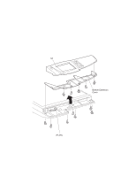
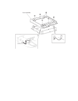
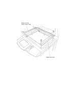
4036-501 User Interface Panel Removal CAUTION: Ensure the scanner power is off before the user interface panel is removed. The back light of the touch screen is powered with high voltage and could harm a servicer, if touched. Warning: Ensure that all external devices are powered off and unplugged from wall outlets. 1. Remove the five (5) screws from the user interface panel. 2. Raise the user interface from the front side. 3. Disconnect P/J25 from the user interface card. Note: When replacing the user interface panel, ensure the DIP switches on the bottom of the user interface panel are set correctly. Position 1 and 2 should be On, while the other positions are set to Off. DADF Repair Procedures 4-49
-
 1
1 -
2
-
3
-
4
-
5
-
6
-
7
-
8
-
9
-
10
-
11
-
12
-
13
-
14
-
15
-
16
-
17
-
18
-
19
-
20
-
21
-
22
-
23
-
24
-
25
-
26
-
27
-
28
-
29
-
30
-
31
-
32
-
33
-
34
-
35
-
36
-
37
-
38
-
39
-
40
-
41
-
42
-
43
-
44
-
45
-
46
-
47
-
48
-
49
-
50
-
51
-
52
-
53
-
54
-
55
-
56
-
57
-
58
-
59
-
60
-
61
-
62
-
63
-
64
-
65
-
66
-
67
-
68
-
69
-
70
-
71
-
72
-
73
-
74
-
75
-
76
-
77
-
78
-
79
-
80
-
81
-
82
-
83
-
84
-
85
-
86
-
87
-
88
-
89
-
90
-
91
-
92
-
93
-
94
-
95
-
96
-
97
-
 98
98 -
 99
99 -
 100
100 -
 101
101 -
 102
102 -
 103
103 -
 104
104 -
 105
105 -
 106
106 -
 107
107 -
 108
108 -
109
-
110
-
111
-
112
-
113
-
114
-
115
-
116
-
117
-
118
-
119
-
120
-
121
-
122
-
123
-
124
-
125
-
126
-
127
-
128
-
129
-
130
-
131
-
132
-
133
-
134
-
135
-
136
-
137
-
138
-
139
-
140
-
141
-
142
-
143
-
144
-
145
-
146
-
147
-
148
-
149
-
150
-
151
-
152
-
153
-
154
-
155
-
156
-
157
-
158
-
159
-
160
-
161
-
162
-
163
-
164
-
165
-
166
-
167
-
168
-
169
-
170
-
171
-
172
-
173
-
174
-
175
-
176
-
177
-
178
-
179
-
180
-
181
-
182
-
183
-
184
-
185
-
186
-
187
-
188
-
189
-
190
-
191
-
192
-
193
-
194
-
195
-
196
 |
 |

DADF Repair Procedures
4-49
4036-501
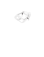
User Interface Panel Removal
CAUTION:
Ensure the scanner power is off before the user interface panel is removed.
The back light of the touch screen is powered with high voltage and could harm a
servicer, if touched.
Warning:
Ensure that all external devices are powered off and unplugged from wall
outlets.
1.
Remove the five (5) screws from the user interface panel.
2.
Raise the user interface from the front side.
3.
Disconnect P/J25 from the user interface card.
Note:
When replacing the user interface panel, ensure the DIP switches on the bottom of
the user interface panel are set correctly. Position 1 and 2 should be
On
, while the other
positions are set to
Off
.