Lexmark X7500 Service Manual - Page 69
DADF Input Tray Assembly Removal
 |
UPC - 734646391306
View all Lexmark X7500 manuals
Add to My Manuals
Save this manual to your list of manuals |
Page 69 highlights
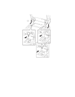
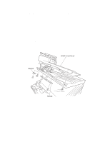
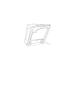
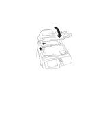
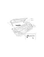
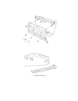
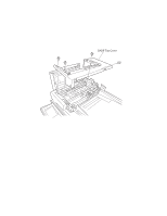
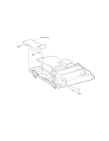
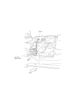
4036-501 DADF Input Tray Assembly Removal 1. Remove the DADF top cover. See "DADF Top Cover Removal" on page 4-18 for more information. 2. Remove the DADF front cover. See "DADF Front Cover, Handle, and Magnet Removal" on page 4-11 for more information. 3. Disconnect connector (P/J30). 4. Unclamp the input tray assembly harness from the frame. 5. Remove the screw and washer (toothed) from the ground wire. 6. Remove the screw from the retaining bracket. 7. Remove the retaining bracket. 8. Open the input tray assembly upward. 9. Remove the screw. Note: This is a shorter screw. 10. Remove the plate. 11. Raise the front side of the input tray assembly, and pull out diagonally upward. DADF Repair Procedures 4-15
-
 1
1 -
2
-
3
-
4
-
5
-
6
-
7
-
8
-
9
-
10
-
11
-
12
-
13
-
14
-
15
-
16
-
17
-
18
-
19
-
20
-
21
-
22
-
23
-
24
-
25
-
26
-
27
-
28
-
29
-
30
-
31
-
32
-
33
-
34
-
35
-
36
-
37
-
38
-
39
-
40
-
41
-
42
-
43
-
44
-
45
-
46
-
47
-
48
-
49
-
50
-
51
-
52
-
53
-
54
-
55
-
56
-
57
-
58
-
59
-
60
-
61
-
62
-
63
-
 64
64 -
 65
65 -
 66
66 -
 67
67 -
 68
68 -
 69
69 -
 70
70 -
 71
71 -
 72
72 -
 73
73 -
 74
74 -
75
-
76
-
77
-
78
-
79
-
80
-
81
-
82
-
83
-
84
-
85
-
86
-
87
-
88
-
89
-
90
-
91
-
92
-
93
-
94
-
95
-
96
-
97
-
98
-
99
-
100
-
101
-
102
-
103
-
104
-
105
-
106
-
107
-
108
-
109
-
110
-
111
-
112
-
113
-
114
-
115
-
116
-
117
-
118
-
119
-
120
-
121
-
122
-
123
-
124
-
125
-
126
-
127
-
128
-
129
-
130
-
131
-
132
-
133
-
134
-
135
-
136
-
137
-
138
-
139
-
140
-
141
-
142
-
143
-
144
-
145
-
146
-
147
-
148
-
149
-
150
-
151
-
152
-
153
-
154
-
155
-
156
-
157
-
158
-
159
-
160
-
161
-
162
-
163
-
164
-
165
-
166
-
167
-
168
-
169
-
170
-
171
-
172
-
173
-
174
-
175
-
176
-
177
-
178
-
179
-
180
-
181
-
182
-
183
-
184
-
185
-
186
-
187
-
188
-
189
-
190
-
191
-
192
-
193
-
194
-
195
-
196
 |
 |

DADF Repair Procedures
4-15
4036-501
DADF Input Tray Assembly Removal
1.
Remove the DADF top cover. See
“DADF Top Cover Removal” on page 4-18
for
more information.
2.
Remove the DADF front cover. See
“DADF Front Cover, Handle, and Magnet
Removal” on page 4-11
for more information.
3.
Disconnect connector (P/J30).
4.
Unclamp the input tray assembly harness from the frame.
5.
Remove the screw and washer (toothed) from the ground wire.
6.
Remove the screw from the retaining bracket.
7.
Remove the retaining bracket.
8.
Open the input tray assembly upward.
9.
Remove the screw.
Note:
This is a shorter screw.
10.
Remove the plate.
11.
Raise the front side of the input tray assembly, and pull out diagonally upward.