Lexmark X7500 Service Manual - Page 82
DADF Main Drive Motor Assembly Removal
 |
UPC - 734646391306
View all Lexmark X7500 manuals
Add to My Manuals
Save this manual to your list of manuals |
Page 82 highlights
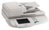
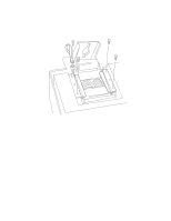
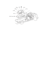
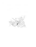
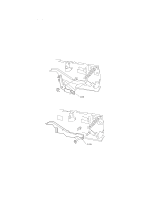
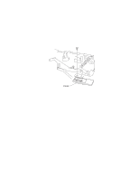
4036-501 DADF Main Drive Motor Assembly Removal 1. Remove the DADF top cover. See "DADF Top Cover Removal" on page 4-18 for more information. 2. Remove the DADF rear cover. See "DADF Rear Cover Removal" on page 4-19 for more information. 3. Release all harnesses from 3 clamps from the DADF main drive motor assembly. 4. Loosen the screw that adjusts the tension roller. 5. Remove the tension spring, and shift the tension roller toward the slackened belt. 6. Disconnect the registration sensor. 7. Thread the cable through the drive motor bracket. 8. Disconnect (P/J20). 9. Disconnect (P/J19). 10.Disconnect (P/J28). 11. Remove the screw (left side) from the ground wire. 12. Remove the screw (right side) from the ground wire. 13. Remove five (5) screws from the DADF assembly. 14. Remove the assembly. 4-28 Service Manual
-
 1
1 -
2
-
3
-
4
-
5
-
6
-
7
-
8
-
9
-
10
-
11
-
12
-
13
-
14
-
15
-
16
-
17
-
18
-
19
-
20
-
21
-
22
-
23
-
24
-
25
-
26
-
27
-
28
-
29
-
30
-
31
-
32
-
33
-
34
-
35
-
36
-
37
-
38
-
39
-
40
-
41
-
42
-
43
-
44
-
45
-
46
-
47
-
48
-
49
-
50
-
51
-
52
-
53
-
54
-
55
-
56
-
57
-
58
-
59
-
60
-
61
-
62
-
63
-
64
-
65
-
66
-
67
-
68
-
69
-
70
-
71
-
72
-
73
-
74
-
75
-
76
-
 77
77 -
 78
78 -
 79
79 -
 80
80 -
 81
81 -
 82
82 -
 83
83 -
 84
84 -
 85
85 -
 86
86 -
 87
87 -
88
-
89
-
90
-
91
-
92
-
93
-
94
-
95
-
96
-
97
-
98
-
99
-
100
-
101
-
102
-
103
-
104
-
105
-
106
-
107
-
108
-
109
-
110
-
111
-
112
-
113
-
114
-
115
-
116
-
117
-
118
-
119
-
120
-
121
-
122
-
123
-
124
-
125
-
126
-
127
-
128
-
129
-
130
-
131
-
132
-
133
-
134
-
135
-
136
-
137
-
138
-
139
-
140
-
141
-
142
-
143
-
144
-
145
-
146
-
147
-
148
-
149
-
150
-
151
-
152
-
153
-
154
-
155
-
156
-
157
-
158
-
159
-
160
-
161
-
162
-
163
-
164
-
165
-
166
-
167
-
168
-
169
-
170
-
171
-
172
-
173
-
174
-
175
-
176
-
177
-
178
-
179
-
180
-
181
-
182
-
183
-
184
-
185
-
186
-
187
-
188
-
189
-
190
-
191
-
192
-
193
-
194
-
195
-
196
 |
 |
