Lexmark X7500 Service Manual - Page 41
Diagnostic Information, Start
 |
UPC - 734646391306
View all Lexmark X7500 manuals
Add to My Manuals
Save this manual to your list of manuals |
Page 41 highlights
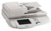
4036-501 2. Diagnostic Information Start CAUTION: Remove power from the scanner system before you connect or disconnect any cable or electronic board or assembly for personal safety and to prevent damage to the scanner system. Warning: It is extremely important not to connect or disconnect the 120-pin scanner cable to the MFD controller cage while the power is on as doing so greatly increases the chance of damaging the Low Voltage Digital Signaling devices in the image processor card and user interface cards. Use the service error codes and service checks in this chapter to determine the corrective action necessary to repair a malfunctioning scanner system. Service error codes for the printer attached to this scanner system can be viewed on the printer's operator panel display. Refer to the printer's service manual for appropriate repair actions. The service error codes for the scanner system are divided into two main categories: Scanner errors and MFD errors. Scanner errors detected by the MFD controller card are displayed to the user interface panel. If an error is reported to the user interface, go to "Scanner Errors" on page 2-2 to determine the corrective action necessary to perform the repair. MFD errors detected by the MFD controller card are displayed to the user interface panel along with an audible beep code and LED code visible on the MFD controller card. If the malfunction is associated with the user interface panel (preventing error messages to be displayed), the beep and LED codes can further assist the servicer in diagnosing the problem. During a full Power-On Self Test, a beep and LED code are generated if a malfunction is detected. Refer to "MFD Controller Cage Errors" on page 2-4 to read the codes and determine the corrective action necessary to perform the repair. If a problem exists with the scanner system unrelated to any of the error codes, go to "Symptom Tables" on page 2-7 to troubleshoot the problem and determine appropriate repair action. Diagnostic Information 2-1
-
 1
1 -
2
-
3
-
4
-
5
-
6
-
7
-
8
-
9
-
10
-
11
-
12
-
13
-
14
-
15
-
16
-
17
-
18
-
19
-
20
-
21
-
22
-
23
-
24
-
25
-
26
-
27
-
28
-
29
-
30
-
31
-
32
-
33
-
34
-
35
-
 36
36 -
 37
37 -
 38
38 -
 39
39 -
 40
40 -
 41
41 -
 42
42 -
 43
43 -
 44
44 -
 45
45 -
 46
46 -
47
-
48
-
49
-
50
-
51
-
52
-
53
-
54
-
55
-
56
-
57
-
58
-
59
-
60
-
61
-
62
-
63
-
64
-
65
-
66
-
67
-
68
-
69
-
70
-
71
-
72
-
73
-
74
-
75
-
76
-
77
-
78
-
79
-
80
-
81
-
82
-
83
-
84
-
85
-
86
-
87
-
88
-
89
-
90
-
91
-
92
-
93
-
94
-
95
-
96
-
97
-
98
-
99
-
100
-
101
-
102
-
103
-
104
-
105
-
106
-
107
-
108
-
109
-
110
-
111
-
112
-
113
-
114
-
115
-
116
-
117
-
118
-
119
-
120
-
121
-
122
-
123
-
124
-
125
-
126
-
127
-
128
-
129
-
130
-
131
-
132
-
133
-
134
-
135
-
136
-
137
-
138
-
139
-
140
-
141
-
142
-
143
-
144
-
145
-
146
-
147
-
148
-
149
-
150
-
151
-
152
-
153
-
154
-
155
-
156
-
157
-
158
-
159
-
160
-
161
-
162
-
163
-
164
-
165
-
166
-
167
-
168
-
169
-
170
-
171
-
172
-
173
-
174
-
175
-
176
-
177
-
178
-
179
-
180
-
181
-
182
-
183
-
184
-
185
-
186
-
187
-
188
-
189
-
190
-
191
-
192
-
193
-
194
-
195
-
196
 |
 |
