LiftMaster 61LM Owners Manual - Page 135
Install Receiver, Changing The Codes
 |
View all LiftMaster 61LM manuals
Add to My Manuals
Save this manual to your list of manuals |
Page 135 highlights
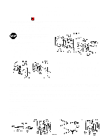
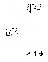
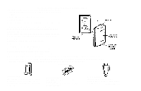
INSTALL RECEIVER DO NOT FASTEN RECEIVER TO A STUD OF AN UNFINISHED GARAGE WALL. ATTACH RECEIVER TO A BOARD , AND THEN FASTEN THE BOARD TO A WALL STUD. FASTEN CAUTION LABEL ON THE WALL NEAT THE RADIO RECEIVER. PROCEDURE: Connect one strand of bell wire to each receiver terminal as shown. Run wire through notch in side of case. The receiver has top and bottom installation flanges. Fasten the receiver to an inside garage wall with the wood screws provided. A convenient place is alongside the service door and OUT OF THE REACH OF CHILDREN. When installing more than one receiver in a garage, place them at least 10 feet apart to prevent electronic interference. Run wire up the wall and across the ceiling to the garage door opener. Use insulated staples. Connect bell wire to the terminals on the back panel of the opener. Plug the antenna into the antenna jack. (See Figure 1 below for antenna location on receiver case). Be careful not to damage the printed circuit board. Plug receiver into a 120 volt outlet. CHANGING THE CODES HOW TO ORDER REPAIR PARTS: Model Numbers are located on the back of Transmitter and on the top of the Receiver. All parts listed herein may be ordered through your local CHAMBERLAIN/LIFTMASTER dealer. When ordering by mail, selling prices will be furnished on request or parts will be shipped at prevailing prices and you will be billed accordingly. ALWAYS GIVE THE FOLLOWING INFORMATION: 1. PART NUMBER; 2. MODEL NUMBER; 3. PART DESCRIPTION; NAME OF ITEM.
-
 1
1 -
2
-
3
-
4
-
5
-
6
-
7
-
8
-
9
-
10
-
11
-
12
-
13
-
14
-
15
-
16
-
17
-
18
-
19
-
20
-
21
-
22
-
23
-
24
-
25
-
26
-
27
-
28
-
29
-
30
-
31
-
32
-
33
-
34
-
35
-
36
-
37
-
38
-
39
-
40
-
41
-
42
-
43
-
44
-
45
-
46
-
47
-
48
-
49
-
50
-
51
-
52
-
53
-
54
-
55
-
56
-
57
-
58
-
59
-
60
-
61
-
62
-
63
-
64
-
65
-
66
-
67
-
68
-
69
-
70
-
71
-
72
-
73
-
74
-
75
-
76
-
77
-
78
-
79
-
80
-
81
-
82
-
83
-
84
-
85
-
86
-
87
-
88
-
89
-
90
-
91
-
92
-
93
-
94
-
95
-
96
-
97
-
98
-
99
-
100
-
101
-
102
-
103
-
104
-
105
-
106
-
107
-
108
-
109
-
110
-
111
-
112
-
113
-
114
-
115
-
116
-
117
-
118
-
119
-
120
-
121
-
122
-
123
-
124
-
125
-
126
-
127
-
128
-
129
-
 130
130 -
 131
131 -
 132
132 -
 133
133 -
 134
134 -
 135
135 -
 136
136 -
 137
137 -
 138
138 -
 139
139 -
 140
140 -
141
-
142
-
143
-
144
-
145
-
146
-
147
-
148
-
149
-
150
-
151
-
152
-
153
-
154
-
155
-
156
-
157
-
158
-
159
-
160
-
161
-
162
-
163
-
164
-
165
-
166
-
167
-
168
-
169
-
170
-
171
-
172
-
173
-
174
-
175
-
176
-
177
-
178
-
179
-
180
-
181
-
182
-
183
-
184
-
185
-
186
-
187
-
188
-
189
-
190
-
191
-
192
-
193
-
194
-
195
-
196
-
197
-
198
-
199
-
200
-
201
-
202
-
203
-
204
-
205
-
206
-
207
-
208
-
209
-
210
-
211
-
212
-
213
-
214
-
215
-
216
-
217
-
218
-
219
-
220
-
221
-
222
-
223
-
224
-
225
-
226
-
227
-
228
-
229
-
230
-
231
-
232
-
233
-
234
-
235
-
236
-
237
-
238
-
239
-
240
-
241
-
242
-
243
-
244
-
245
-
246
-
247
-
248
-
249
-
250
-
251
-
252
-
253
-
254
-
255
-
256
-
257
-
258
-
259
-
260
-
261
-
262
-
263
-
264
-
265
-
266
-
267
-
268
-
269
-
270
-
271
-
272
-
273
-
274
-
275
-
276
-
277
-
278
-
279
-
280
-
281
-
282
-
283
-
284
-
285
-
286
 |
 |
