LiftMaster 61LM Owners Manual - Page 138
Series 72, Indoor/outdoor Wire-in Light Control
 |
View all LiftMaster 61LM manuals
Add to My Manuals
Save this manual to your list of manuals |
Page 138 highlights
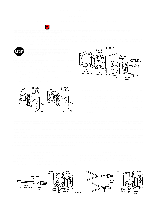
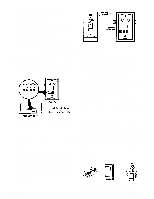
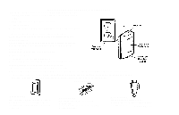
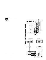
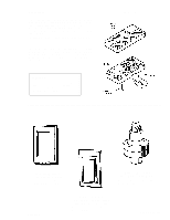
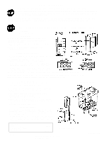
OWNERS MANUAL SERIES 72 INDOOR/OUTDOOR WIRE-IN LIGHT CONTROL FOR INSIDE USE ONLY WITH INCANDESCENT LAMP CIRCUITS OF 500 WATTS OR LESS. NOT FOR USE IN CIRCUITS WITH FLUORESCENT LAMPS OR WITH LIGHT DIMMERS. The Wire-in Control can be operated by any Series 50, 51, 52, 53 or Model 73 transmitter. The Wire-in Control consists of two parts: the power supply and the receiver. It can replace either single pole (1 switch controlling a single light) or 3way switches (2 switches controlling a single light). Depending on the 3-way switch wiring, light may turn on after a power failure. If properly wired, this will not occur with a single pole switch installation. TURN OFF THE POWER TO CIRCUIT AT FUSE BOX OR CIRCUIT BREAKER BEFORE BEGINNING INSTALLATION Figure 1 illustrates the installation of receiver and power supply to junction box in interior wall. 1. Pry up lower edge of actuator button until it separates from receiver housing. Set actuator aside. 2. Remove the 6-32"x1-1/2" screw and unplug receiver from power supply. Set receiver aside. 3. Remove wall plate and set aside for re-assembly. 4. Remove screws holding switch to junction box. _____ 5. Pull switch from the junction box in order to access the connecting terminals. On 3-way switches, mark the common terminal wire before disconnecting. (Common terminal may be marked "common", "com" - or uses a different color screw (gold or silver) than the other two terminal screws.) 6. Disconnect wires from switch. Straighten the ends and make sure that insulation is trimmed back 1/2" to allow connection of power supply wires. _____ Transmitter range will vary depending on your house and wiring construction. Metal lath, foil-backed insulation or aluminum siding will reduce range. After installation is complete, test transmitter operation at various locations within your home for convenience and range. SINGLE POLE SWITCH: If transmission range Is noticeably shorter when turning light OFF than when turning light ON, reverse wiring connections. 3-WAY SWITCH: It transmission range Is noticeably shorter when turning light OFF than when turning light ON, the Wire-in Control needs to be installed in the other switching location. (The black wire in the Wire-in Control must be connected to the "hot" junction box wire.) CAUTION: If there is a ground on your switch (usually a bare wire attached to a green screw on switch), connect wire to the metal junction __b_o_x_. _If_b_o_x__is_p_l_a_st_ic_,_c_o_n_n_e_c_t _w_ir_e_t_o_m_e_t_a_l _pa_r_t_o_f_W_i_re_-_in__C_o_n_tr_o_l SINGLE POLE SWITCH Fold the BLUE power supply wire back as shown and cap with wire nut. Screw nut in clockwise direction to secure. Cap black control wire to one junction box wire and red conrol wire to the other. Screw wire nuts on clockwise, making sure bare wires are covered. 3-WAY SWITCH Start by capping the black control wire to the COMMON "hot or live" wire; the red and blue control wires separately to the other two junction box wires in any order. Screw wire nuts on clockwise making sure bare wires are covered.
-
 1
1 -
2
-
3
-
4
-
5
-
6
-
7
-
8
-
9
-
10
-
11
-
12
-
13
-
14
-
15
-
16
-
17
-
18
-
19
-
20
-
21
-
22
-
23
-
24
-
25
-
26
-
27
-
28
-
29
-
30
-
31
-
32
-
33
-
34
-
35
-
36
-
37
-
38
-
39
-
40
-
41
-
42
-
43
-
44
-
45
-
46
-
47
-
48
-
49
-
50
-
51
-
52
-
53
-
54
-
55
-
56
-
57
-
58
-
59
-
60
-
61
-
62
-
63
-
64
-
65
-
66
-
67
-
68
-
69
-
70
-
71
-
72
-
73
-
74
-
75
-
76
-
77
-
78
-
79
-
80
-
81
-
82
-
83
-
84
-
85
-
86
-
87
-
88
-
89
-
90
-
91
-
92
-
93
-
94
-
95
-
96
-
97
-
98
-
99
-
100
-
101
-
102
-
103
-
104
-
105
-
106
-
107
-
108
-
109
-
110
-
111
-
112
-
113
-
114
-
115
-
116
-
117
-
118
-
119
-
120
-
121
-
122
-
123
-
124
-
125
-
126
-
127
-
128
-
129
-
130
-
131
-
132
-
 133
133 -
 134
134 -
 135
135 -
 136
136 -
 137
137 -
 138
138 -
 139
139 -
 140
140 -
 141
141 -
 142
142 -
 143
143 -
144
-
145
-
146
-
147
-
148
-
149
-
150
-
151
-
152
-
153
-
154
-
155
-
156
-
157
-
158
-
159
-
160
-
161
-
162
-
163
-
164
-
165
-
166
-
167
-
168
-
169
-
170
-
171
-
172
-
173
-
174
-
175
-
176
-
177
-
178
-
179
-
180
-
181
-
182
-
183
-
184
-
185
-
186
-
187
-
188
-
189
-
190
-
191
-
192
-
193
-
194
-
195
-
196
-
197
-
198
-
199
-
200
-
201
-
202
-
203
-
204
-
205
-
206
-
207
-
208
-
209
-
210
-
211
-
212
-
213
-
214
-
215
-
216
-
217
-
218
-
219
-
220
-
221
-
222
-
223
-
224
-
225
-
226
-
227
-
228
-
229
-
230
-
231
-
232
-
233
-
234
-
235
-
236
-
237
-
238
-
239
-
240
-
241
-
242
-
243
-
244
-
245
-
246
-
247
-
248
-
249
-
250
-
251
-
252
-
253
-
254
-
255
-
256
-
257
-
258
-
259
-
260
-
261
-
262
-
263
-
264
-
265
-
266
-
267
-
268
-
269
-
270
-
271
-
272
-
273
-
274
-
275
-
276
-
277
-
278
-
279
-
280
-
281
-
282
-
283
-
284
-
285
-
286
 |
 |
