LiftMaster 61LM Owners Manual - Page 143
Owners Manual
 |
View all LiftMaster 61LM manuals
Add to My Manuals
Save this manual to your list of manuals |
Page 143 highlights
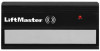
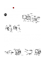
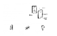
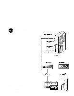
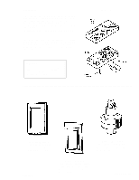
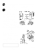
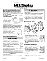
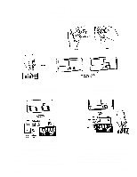
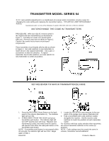
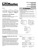
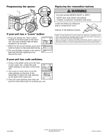
Owners Manual 3-Channel Transmitter With Wall Mount-Model 73 CAUTION: ACTIVATE GARAGE DOOR OPENER ONLY WHEN THE DOOR IS IN FULL VIEW, FREE OF OBSTRUCTION AND OPENER IS PROPERLY ADJUSTED. NO ONE SHOULD ENTER OR LEAVE THE GARAGE WHILE DOOR IS IN MOTION. DO NOT ALLOW CHILDREN TO PLAY NEAR DOOR. Each push button on the transmitter can activate one or more remote control devices, including any 19,683 code garage door opener. Remove transmitter from wall mount. Follow code setting/changing instructions below before installing wall mount case. _____ DISCONNECT THE POWER TO THE OPENER (OR OTHER DEVICES) BEFORE SETTING OR CHANGING RECEIVER CODE. RECEIVER Locate the receiver code switch block TRANSMITTER Decide which of the transmitter push buttons you want to use to operate the receiver. The push button with the battery test light indicator is the TOP button. 1. Remove the transmitter cover screw. Carefully turn the case over (push button side up). 2. Remove the case top. CAUTION: be careful not to move the circuit board components SETTING/CHANGING THE CODE 1. Use a pen or screwdriver to slide one or more of the TRANSMITTER code switches to a plus ( + ), center (0) or minus ( - ) position. 2. Set RECEIVER code switch #1 to match the transmitter push button you want to use with that receiver ( +, 0 or - ). Refer to illustration. 3. Hold transmitter circuit board alongside receiver. Beginning with RECEIVER code switch #2, match position of each transmitter switch. 4. If you have additional receivers, match the code settings of the transmiter (2 through 9) and slide receiver code switch #1 to the position which matches an unused push button. NOTE 1: For receivers with less code switches than transmitter, set excess transmitter switches to the center (0) position. NOTE 2: Code switches 2 through 9 on ALL receivers operated by this transmitter must MATCH switches 2 through 9 in transmitter. CA_U_T_I_O_N_: _If_y_ou__p_re_s_s_m_o_r_e_t_h_an__O_N_E_p_u_sh__b_ut_to_n__a_t t_h_e_s_am__e_ti_m_e_, t_ra_n_s_m_it_te_r_w_il_l _no_t_o_p_e_ra_te IN. . .S_TALL WALL M_O_ UNT Transmiter range will vary depending on your house construction. Metal lath, foil-backed insulation or aluminum siding will reduce range. TRANSMITTER Before permanently installing wall mount on an interior wall, test the transmitter operation at various locations within your home for convenience and range. If any push button will be used to operate a garage door opener, choose a location out of reach of children. 1. Position wall mount and mark both fastening locations. 2. Plastic anchors are provided, if required for your installation. Drill 3/16" holes and insert the anchors. Use a hammer to "flush-up" anchor heads to wall. 3. Use #6x1" screws provided. Tighten securely TRANSMITTER BATTERY A 9 volt battery should produce power for at least one year. As long as there is adequate power, battery test light will glow when push button is pressed. When the light does not come on, replace battery. If transmission range lessens, check battery light. TO CHANGE BATTERY: Remove visor clip and connecting screw in transmitter case. Set aside top of case and discard old battery. Snap connector onto new battery. Replace the top of case and the connecting screw. Replace visor clip. PARTS LIST Battery Case, Cover & Screw (Circuit board not included) Wall Mount Assy. 114A1100 10A15 41 A3072 41A3136 WALL MOUNT © 1988, The Chamberlain Group, Inc. All rights reserved Printed in Mexico
-
 1
1 -
2
-
3
-
4
-
5
-
6
-
7
-
8
-
9
-
10
-
11
-
12
-
13
-
14
-
15
-
16
-
17
-
18
-
19
-
20
-
21
-
22
-
23
-
24
-
25
-
26
-
27
-
28
-
29
-
30
-
31
-
32
-
33
-
34
-
35
-
36
-
37
-
38
-
39
-
40
-
41
-
42
-
43
-
44
-
45
-
46
-
47
-
48
-
49
-
50
-
51
-
52
-
53
-
54
-
55
-
56
-
57
-
58
-
59
-
60
-
61
-
62
-
63
-
64
-
65
-
66
-
67
-
68
-
69
-
70
-
71
-
72
-
73
-
74
-
75
-
76
-
77
-
78
-
79
-
80
-
81
-
82
-
83
-
84
-
85
-
86
-
87
-
88
-
89
-
90
-
91
-
92
-
93
-
94
-
95
-
96
-
97
-
98
-
99
-
100
-
101
-
102
-
103
-
104
-
105
-
106
-
107
-
108
-
109
-
110
-
111
-
112
-
113
-
114
-
115
-
116
-
117
-
118
-
119
-
120
-
121
-
122
-
123
-
124
-
125
-
126
-
127
-
128
-
129
-
130
-
131
-
132
-
133
-
134
-
135
-
136
-
137
-
 138
138 -
 139
139 -
 140
140 -
 141
141 -
 142
142 -
 143
143 -
 144
144 -
 145
145 -
 146
146 -
 147
147 -
 148
148 -
149
-
150
-
151
-
152
-
153
-
154
-
155
-
156
-
157
-
158
-
159
-
160
-
161
-
162
-
163
-
164
-
165
-
166
-
167
-
168
-
169
-
170
-
171
-
172
-
173
-
174
-
175
-
176
-
177
-
178
-
179
-
180
-
181
-
182
-
183
-
184
-
185
-
186
-
187
-
188
-
189
-
190
-
191
-
192
-
193
-
194
-
195
-
196
-
197
-
198
-
199
-
200
-
201
-
202
-
203
-
204
-
205
-
206
-
207
-
208
-
209
-
210
-
211
-
212
-
213
-
214
-
215
-
216
-
217
-
218
-
219
-
220
-
221
-
222
-
223
-
224
-
225
-
226
-
227
-
228
-
229
-
230
-
231
-
232
-
233
-
234
-
235
-
236
-
237
-
238
-
239
-
240
-
241
-
242
-
243
-
244
-
245
-
246
-
247
-
248
-
249
-
250
-
251
-
252
-
253
-
254
-
255
-
256
-
257
-
258
-
259
-
260
-
261
-
262
-
263
-
264
-
265
-
266
-
267
-
268
-
269
-
270
-
271
-
272
-
273
-
274
-
275
-
276
-
277
-
278
-
279
-
280
-
281
-
282
-
283
-
284
-
285
-
286
 |
 |