LiftMaster 61LM Owners Manual - Page 139
Power Supply, Receiver
 |
View all LiftMaster 61LM manuals
Add to My Manuals
Save this manual to your list of manuals |
Page 139 highlights
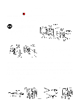
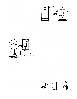
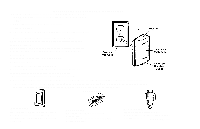
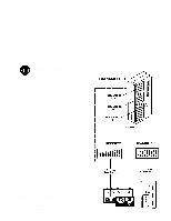
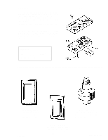
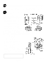
7. Carefully pack the wiring back into junction box. Make sure wires are not pinched or strained. 8. Fasten power supply to junction box with the #6x1-1/2" flat-head screws provided. 9. Move power supply switch to the right. Move receiver slide bar so "OFF" is visible. The control will be OFF. 10. Refer to Figure 1. Position wall plate over the junction box. Align receiver so that three-pin plug engages holes in power supply and slide bar engages the power supply switch. Insert (2) #6-32x1-1/2" screws through fastening holes in receiver, wall plate and power supply. Tighten securely. Do not replace the actuator push button until you have set the code. See instructions below. POWER SUPPLY RECEIVER _____ PROCEDURE FOR SETTING OR CHANGING THE CODE The Wire-in Control receiver and transmiter must be set with matching codes. To set (or change the code for any reason follow instructions below. The receiver code switches are located on the front of the unit, behind the actuator. The switch code block with plus (+), (0) and minus(-) positions provide 19,683 possible code settings. WITH MULTI FUNCTION TRANSMITTER Follow instructions packed with your multi function transmitter. Reassemble transmitter cover case. Snap the actuator cover onto receiver. Turn on the power to circuit. Move receiver slide bar so "ON" is visible. Control will be ON. WITH SINGLE CHANNEL TRANSMITTER Remove the transmitter cover screw. Turn case over (push button side up). CAUTION: Be careful not to move circuit board components. Set (or change) code in receiver by sliding one or more of the 9 code switches to a plus, (0) or minus position. Hold transmitter circuit board alongside receiver code switch block. Set code switches in transmitter to match positions of receiver code switches. Reassemble transmitter case. Snap actuator cover onto receiver. Turn on the power to circuit. Move receiver slide bar so "ON" is visible. Control will be ON. _____ 11. TO TEST: press actuator push button. Light should turn on. Press again, Light should turn off. Press transmitter push button. Light should turn on. Press again and light should turn off. NOTE: Allow a 1-second interval between transmitter operations. 12. If light does not operate. check to be sure: • Power is ON. Check fuse box or circuit breaker. • Light bulb is "good". • Receiver is firmly connected to power supply and slide bar is in ON position, • Electrical wiring is correct. Review the wiring instructions on Side 1. • Receiver and transmitter have matching code settings. • You are pressing the transmitter push button selected to operate Wire-in (on multi function transmitters). • Transmitters battery has power. NOTE: Test light on the transmitter should glow when push button is pressed. (Battery changing information is included in instructions packed with your transmitter). CAUTION: TO AVOID ELECTRIC SHOCK,move the slide switch to the OFF position whenever It is necessary to change a light bulb. IMPORTANT NOTE: If you use less than a 40 Watt bulb, the lamp may glow dimly when OFF. This is normal. If two or more Light Products are installed, they must be located at least 10 feet apart to prevent electronic Interference. There is a selection of accessories for use with the multi function remote transmitter: Series 53 Multifunction Remote Transmitter Series 74 Appliance Control Receiver Module Series 71 Indoor/Outdoor Receiver Module 114A1056 Printed in Mexico
-
 1
1 -
2
-
3
-
4
-
5
-
6
-
7
-
8
-
9
-
10
-
11
-
12
-
13
-
14
-
15
-
16
-
17
-
18
-
19
-
20
-
21
-
22
-
23
-
24
-
25
-
26
-
27
-
28
-
29
-
30
-
31
-
32
-
33
-
34
-
35
-
36
-
37
-
38
-
39
-
40
-
41
-
42
-
43
-
44
-
45
-
46
-
47
-
48
-
49
-
50
-
51
-
52
-
53
-
54
-
55
-
56
-
57
-
58
-
59
-
60
-
61
-
62
-
63
-
64
-
65
-
66
-
67
-
68
-
69
-
70
-
71
-
72
-
73
-
74
-
75
-
76
-
77
-
78
-
79
-
80
-
81
-
82
-
83
-
84
-
85
-
86
-
87
-
88
-
89
-
90
-
91
-
92
-
93
-
94
-
95
-
96
-
97
-
98
-
99
-
100
-
101
-
102
-
103
-
104
-
105
-
106
-
107
-
108
-
109
-
110
-
111
-
112
-
113
-
114
-
115
-
116
-
117
-
118
-
119
-
120
-
121
-
122
-
123
-
124
-
125
-
126
-
127
-
128
-
129
-
130
-
131
-
132
-
133
-
 134
134 -
 135
135 -
 136
136 -
 137
137 -
 138
138 -
 139
139 -
 140
140 -
 141
141 -
 142
142 -
 143
143 -
 144
144 -
145
-
146
-
147
-
148
-
149
-
150
-
151
-
152
-
153
-
154
-
155
-
156
-
157
-
158
-
159
-
160
-
161
-
162
-
163
-
164
-
165
-
166
-
167
-
168
-
169
-
170
-
171
-
172
-
173
-
174
-
175
-
176
-
177
-
178
-
179
-
180
-
181
-
182
-
183
-
184
-
185
-
186
-
187
-
188
-
189
-
190
-
191
-
192
-
193
-
194
-
195
-
196
-
197
-
198
-
199
-
200
-
201
-
202
-
203
-
204
-
205
-
206
-
207
-
208
-
209
-
210
-
211
-
212
-
213
-
214
-
215
-
216
-
217
-
218
-
219
-
220
-
221
-
222
-
223
-
224
-
225
-
226
-
227
-
228
-
229
-
230
-
231
-
232
-
233
-
234
-
235
-
236
-
237
-
238
-
239
-
240
-
241
-
242
-
243
-
244
-
245
-
246
-
247
-
248
-
249
-
250
-
251
-
252
-
253
-
254
-
255
-
256
-
257
-
258
-
259
-
260
-
261
-
262
-
263
-
264
-
265
-
266
-
267
-
268
-
269
-
270
-
271
-
272
-
273
-
274
-
275
-
276
-
277
-
278
-
279
-
280
-
281
-
282
-
283
-
284
-
285
-
286
 |
 |
