Magnavox MWR20V6 Owners Manual - Page 14
Connections
 |
UPC - 053818570180
View all Magnavox MWR20V6 manuals
Add to My Manuals
Save this manual to your list of manuals |
Page 14 highlights
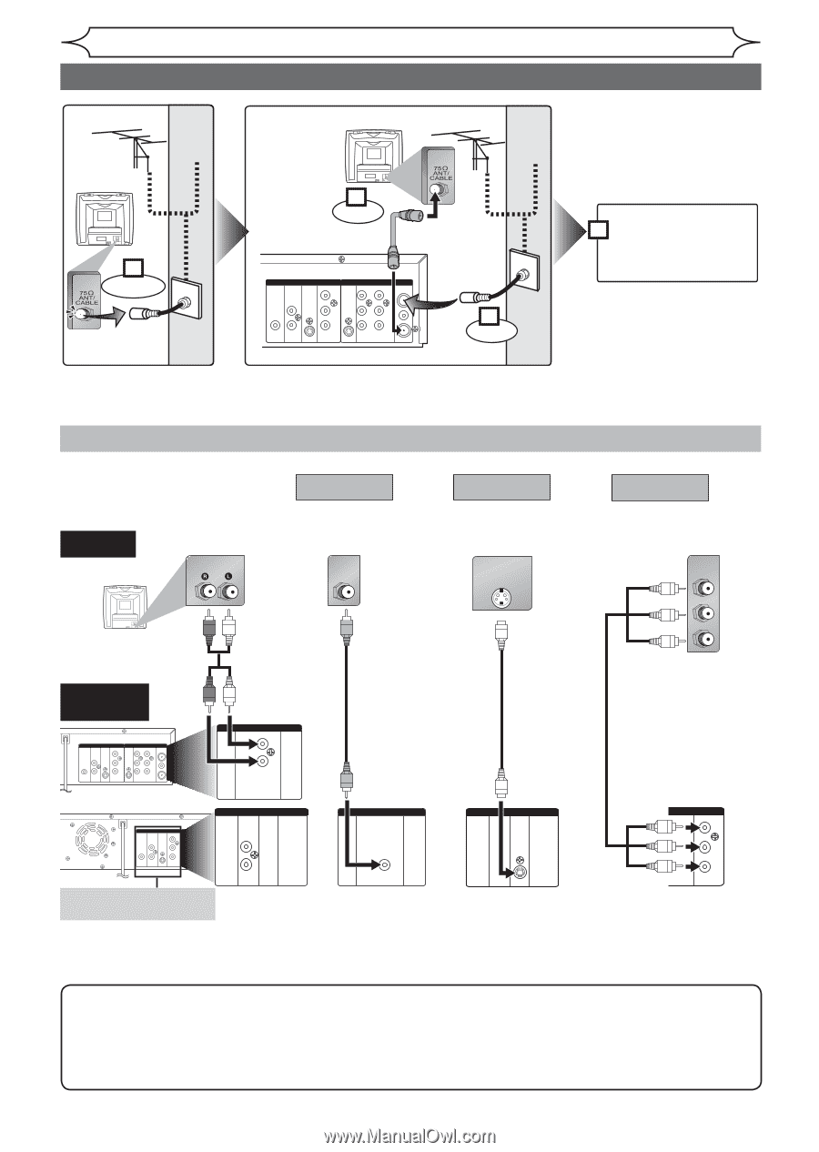
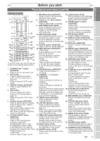
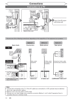
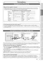
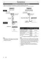
Antenna Cable TV signal (Back of TV) or 1 Disconnect Connections Connection to a TV (Back of TV) Antenna Cable TV signal 3 Connect RF cable (supplied) DIGITAL AUDIO OUT DVD AUDIO S-VIDEO OUT COMPONENT VIDEO OUT Y S-VIDEO DVD/VCR IN - AUDIO - OUT L L ANTENNA IN COAXIAL L OUT R PB /CB IN PR /CR R R IN - VIDEO - OUT OUT (Back of this unit) or 2 Connect 4 Plug in the AC power cord of this unit. Choose one of the following connections, depending on the capabilities of the equipment you possess. Basic Audio TV AUDIO IN Method 1 Good picture VIDEO IN Audio cable (supplied) This unit DVD DIGITAL AUDIO S-VIDEO AUDIO OUT OUT COMPONENT VIDEO OUT Y S-VIDEO DVD/VCR IN - AUDIO - OUT L L ANTENNA IN COAXIAL L OUT R PB /CB IN PR /CR R R IN - VIDEO - OUT OUT DVD DIGITAL AUDIO S-VIDEO AUDIO OUT OUT COMPONENT VIDEO OUT Y DVD/VCR S-VIDEO IN - AUDIO - OUT L L ANTENNA IN COAXIAL L OUT R PB /CB IN R R IN - VIDEO - OUT PR /CR OUT DVD/VCR IN - AUDIO - OUT L R or DVD AUDIO OUT L R • These jacks are useful AUDIO OUT only in DVD mode. Video cable (supplied) DVD/VCR IN - VIDEO - OUT VIDEO OUT Method 2 Better picture S-VIDEO IN Method 3 Best picture COMPONENT VIDEO IN Y PB/CB PR/CR S-Video cable (commercially available) Component video cable (commercially available) DVD S-VIDEO OUT S-VIDEO OUT DVD COMPONENT VIDEO OUT Y PB /CB PR /CR COMPONENT VIDEO OUT Note • Connect this unit directly to the TV. If the A/V cables are connected to a VCR, pictures may be distorted due to the copy protection system. • Method 2 and 3 are only useful in DVD mode. • Although you can view images when using the connection Method 1 and 2 while Progressive Scan is activated, they are in Interlace mode. 14 EN
-
 1
1 -
2
-
3
-
4
-
5
-
6
-
7
-
8
-
 9
9 -
 10
10 -
 11
11 -
 12
12 -
 13
13 -
 14
14 -
 15
15 -
 16
16 -
 17
17 -
 18
18 -
 19
19 -
20
-
21
-
22
-
23
-
24
-
25
-
26
-
27
-
28
-
29
-
30
-
31
-
32
-
33
-
34
-
35
-
36
-
37
-
38
-
39
-
40
-
41
-
42
-
43
-
44
-
45
-
46
-
47
-
48
-
49
-
50
-
51
-
52
-
53
-
54
-
55
-
56
-
57
-
58
-
59
-
60
-
61
-
62
-
63
-
64
-
65
-
66
-
67
-
68
-
69
-
70
-
71
-
72
-
73
-
74
-
75
-
76
-
77
-
78
-
79
-
80
-
81
-
82
-
83
-
84
-
85
-
86
-
87
-
88
-
89
-
90
 |
 |