Panasonic WJRT208 WJRT208 User Guide - Page 18
Important, When connecting a single unit with a controller, System controller: WV-CU650
 |
View all Panasonic WJRT208 manuals
Add to My Manuals
Save this manual to your list of manuals |
Page 18 highlights
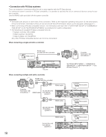
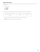
• Connection with PS·Data systems This is an example of connection when the unit is used together with the PS·Data devices. If a connected system controller is PS·Data compatible, it is possible to operate this unit or connected devices using the system controller. Use the RS485 cable provided with the system controller. Important: • Terminate both devices on both ends of the connection. Refer to the respective operating instructions for the descriptions of how to terminate. Termination of this unit can be set with the DIP termination switch on the rear panel. (See page 21.) • When connecting a PS·Data compatible device, it is necessary to set each item of "DATA PORT SETUP" of "COMMUNICATION SETUP" on the "WJ-RT208 SETUP MENU" according to the system configuration. • The following are available PS·Data compatible devices. • System controller: WV-CU650 • Matrix switcher: WJ-SX150 • Data multiplex unit: WJ-MP204 (Any other PS·Data compatible devices are not to be connected.) When connecting a single unit with a controller ON Mode switch 12 RS485 cable (provided with the controller) ON OFF POWER SIGNAL GND AC IN AUDIO OUT AUDIO IN 1 2 3 4 5 6 7 8 TERMINAL/CONTROL 1 2 3 4 5 6 7 8 MODE DATA 10/100BASE-T COPY1 SERIAL MONITOR(VGA) VIDEO OUT VIDEO IN This unit SYSTEM CONTROLLER 123 456 789 0 A B Controller Termination: ON Unit address: 1 "WJ-RT208 SETUP MENU" → "COMMUNICATION SETUP" → "DATA PORT SETUP" → "Unit Address (System)": 1 When connecting multiple units with a controller SYSTEM CONTROLLER 123 456 789 0 RS485 cable (provided with the controller) A B Controller Termination: ON Unit address: 1 1st unit (this unit) RS485 cable Unit address (system): 1 RS485 cable ON Mode switch 12 ON OFF POWER SIGNAL GND AC IN AUDIO OUT AUDIO IN 1 2 3 4 5 6 7 8 TERMINAL/CONTROL 1 2 3 4 5 6 7 8 MODE DATA 10/100BASE-T COPY1 SERIAL MONITOR(VGA) VIDEO OUT VIDEO IN RS485 cable ON Mode switch 12 2nd unit (this unit) Unit address (system): 2 ON OFF POWER SIGNAL GND AC IN AUDIO OUT AUDIO IN 1 2 3 4 5 6 7 8 TERMINAL/CONTROL 1 2 3 4 5 6 7 8 MODE DATA 10/100BASE-T COPY1 SERIAL MONITOR(VGA) VIDEO OUT VIDEO IN RS485 cable ON Mode switch 12 3rd unit (this unit) Unit address (system): 3 ON OFF POWER SIGNAL GND AC IN AUDIO OUT AUDIO IN 1 2 3 4 5 6 7 8 TERMINAL/CONTROL 1 2 3 4 5 6 7 8 MODE DATA 10/100BASE-T COPY1 SERIAL MONITOR(VGA) VIDEO OUT VIDEO IN 18
-
 1
1 -
2
-
3
-
4
-
5
-
6
-
7
-
8
-
9
-
10
-
11
-
12
-
 13
13 -
 14
14 -
 15
15 -
 16
16 -
 17
17 -
 18
18 -
 19
19 -
 20
20 -
 21
21 -
 22
22 -
 23
23 -
24
-
25
-
26
-
27
-
28
-
29
-
30
-
31
-
32
-
33
-
34
-
35
-
36
-
37
-
38
-
39
-
40
-
41
-
42
-
43
-
44
-
45
-
46
-
47
-
48
-
49
-
50
-
51
-
52
-
53
-
54
-
55
-
56
-
57
-
58
-
59
-
60
-
61
-
62
 |
 |
