Panasonic WJRT208 WJRT208 User Guide - Page 19
When using WJ-SX150, Termination:
 |
View all Panasonic WJRT208 manuals
Add to My Manuals
Save this manual to your list of manuals |
Page 19 highlights
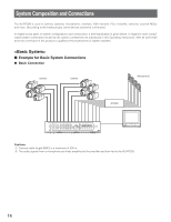
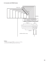
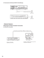
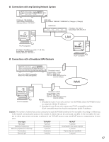
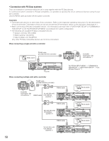
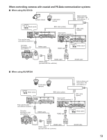
When controlling cameras with coaxial and PS·Data communication systems ■ When using WJ-SX150 System camera Combination camera Matrix switcher Termination: ON Unit address: 1 - 4 ON Mode switch 12 BNC cable (option) BNC cable (option) ON OFF POWER SIGNAL GND AC IN AUDIO OUT AUDIO IN 1 2 3 4 5 6 7 8 TERMINAL/CONTROL 1 2 3 4 5 6 7 8 MODE DATA 10/100BASE-T COPY1 SERIAL MONITOR(VGA) VIDEO OUT VIDEO IN First unit (this unit) Unit address (system): 5 Second unit Unit address (system): 6 ON OFF POWER SIGNAL GND AC IN AUDIO OUT AUDIO IN 1 2 3 4 5 6 7 8 TERMINAL/CONTROL 1 2 3 4 5 6 7 8 MODE DATA 10/100BASE-T COPY1 SERIAL MONITOR(VGA) VIDEO OUT VIDEO IN Controller Termination: ON Unit address: 1 RS485 cable RS485 cable ON Mode switch 12 SYSTEM CONTROLLER 123 456 789 0 A B RS485 cable RS485 cable (provided with the controller) RS485 cable ■ When using WJ-MP204 Combination cameras Data multiplex unit Termination: ON Unit address: 3 ON Mode switch 12 BNC cable (option) BNC cable (option) ON OFF POWER SIGNAL GND AC IN AUDIO OUT AUDIO IN 1 2 3 4 5 6 7 8 TERMINAL/CONTROL 1 2 3 4 5 6 7 8 MODE DATA 10/100BASE-T COPY1 SERIAL MONITOR(VGA) VIDEO OUT VIDEO IN First unit (this unit) Unit address (system): 1 Second unit Unit address (system): 2 ON OFF POWER SIGNAL GND AC IN AUDIO OUT AUDIO IN 1 2 3 4 5 6 7 8 TERMINAL/CONTROL 1 2 3 4 5 6 7 8 MODE DATA 10/100BASE-T COPY1 SERIAL MONITOR(VGA) VIDEO OUT VIDEO IN Controller Termination: ON Unit address: 1 RS485 cable RS485 cable ON Mode switch 12 SYSTEM CONTROLLER 123 456 789 0 A B RS485 cable RS485 cable (provided with the controller) RS485 cable 19
-
 1
1 -
2
-
3
-
4
-
5
-
6
-
7
-
8
-
9
-
10
-
11
-
12
-
13
-
 14
14 -
 15
15 -
 16
16 -
 17
17 -
 18
18 -
 19
19 -
 20
20 -
 21
21 -
 22
22 -
 23
23 -
 24
24 -
25
-
26
-
27
-
28
-
29
-
30
-
31
-
32
-
33
-
34
-
35
-
36
-
37
-
38
-
39
-
40
-
41
-
42
-
43
-
44
-
45
-
46
-
47
-
48
-
49
-
50
-
51
-
52
-
53
-
54
-
55
-
56
-
57
-
58
-
59
-
60
-
61
-
62
 |
 |
