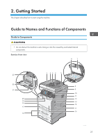
Ricoh SP 4510SF User Guide - Page 30
Interior: Front view, USB 2.0 [Type B] port
 |
View all Ricoh SP 4510SF manuals
Add to My Manuals
Save this manual to your list of manuals |
Page 30 highlights
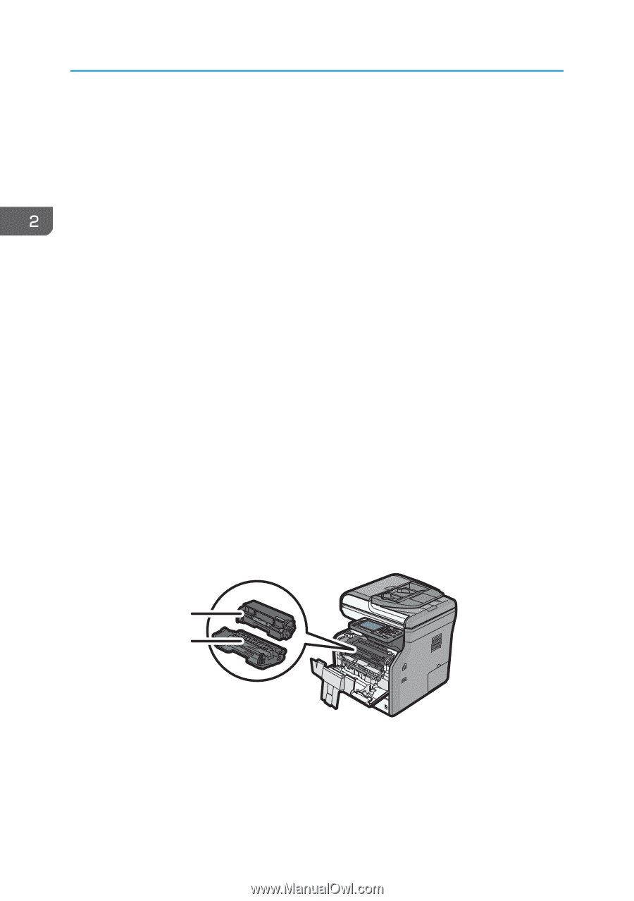
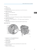
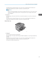
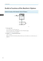
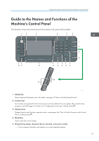
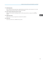
2. Getting Started 5. Rear cover Open to access the inside of the machine and remove jammed paper. Open here to replace the fusing unit. 6. Gigabit Ethernet port Use a network interface cable to connect the machine to a network. 7. USB 2.0 [Type B] port Use a USB cable to connect the machine to a computer. 8. Security slot Connect a security cable to prevent theft. 9. USB port H (Port for use by customer engineer) Do not use this port. 10. Slot Optional interface boards can be inserted. Insert an optional wireless LAN interface board, file format converter or IEEE 1284 interface board. 11. Expansion card slots Remove the cover to install SD cards. 12. External telephone connector For connecting an external telephone. 13. G3 interface unit connector For connecting a telephone line. 14. USB Host Interface Connect external devices such as a card authentication device. Interior: Front view 1 2 CXC403 1. Toner cartridge Pull out the toner cartridge and remove jammed paper. Messages appear on the screen when the toner cartridge needs to be replaced, or a new cartridge needs to be prepared. 28
-
 1
1 -
2
-
3
-
4
-
5
-
6
-
7
-
8
-
9
-
10
-
11
-
12
-
13
-
14
-
15
-
16
-
17
-
18
-
19
-
20
-
21
-
22
-
23
-
24
-
 25
25 -
 26
26 -
 27
27 -
 28
28 -
 29
29 -
 30
30 -
 31
31 -
 32
32 -
 33
33 -
 34
34 -
 35
35 -
36
-
37
-
38
-
39
-
40
-
41
-
42
-
43
-
44
-
45
-
46
-
47
-
48
-
49
-
50
-
51
-
52
-
53
-
54
-
55
-
56
-
57
-
58
-
59
-
60
-
61
-
62
-
63
-
64
-
65
-
66
-
67
-
68
-
69
-
70
-
71
-
72
-
73
-
74
-
75
-
76
-
77
-
78
-
79
-
80
-
81
-
82
-
83
-
84
-
85
-
86
-
87
-
88
-
89
-
90
-
91
-
92
-
93
-
94
-
95
-
96
-
97
-
98
-
99
-
100
-
101
-
102
-
103
-
104
-
105
-
106
-
107
-
108
-
109
-
110
-
111
-
112
-
113
-
114
-
115
-
116
-
117
-
118
-
119
-
120
-
121
-
122
-
123
-
124
-
125
-
126
-
127
-
128
-
129
-
130
-
131
-
132
-
133
-
134
-
135
-
136
-
137
-
138
-
139
-
140
-
141
-
142
-
143
-
144
-
145
-
146
-
147
-
148
-
149
-
150
-
151
-
152
-
153
-
154
-
155
-
156
-
157
-
158
-
159
-
160
-
161
-
162
-
163
-
164
-
165
-
166
-
167
-
168
-
169
-
170
-
171
-
172
-
173
-
174
-
175
-
176
-
177
-
178
-
179
-
180
-
181
-
182
-
183
-
184
-
185
-
186
-
187
-
188
-
189
-
190
-
191
-
192
-
193
-
194
-
195
-
196
-
197
-
198
-
199
-
200
-
201
-
202
-
203
-
204
-
205
-
206
-
207
-
208
-
209
-
210
-
211
-
212
-
213
-
214
-
215
-
216
-
217
-
218
-
219
-
220
-
221
-
222
-
223
-
224
 |
 |