Sharp MX-2310U Installation Manual - Page 51
MX-PN11A/B/C/D (PUNCH MODULE), 1. Unpacking, A. Check the packed items, 2. Installation, A. Removal
 |
View all Sharp MX-2310U manuals
Add to My Manuals
Save this manual to your list of manuals |
Page 51 highlights
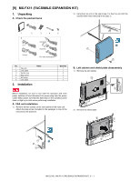
M[7X-]2310MU X-PN11A/B/C/D (PUNCH MODULE)Service Manual 1. Unpacking A. Check the packed items A. Removal of the open/close cover and the path guide 1) Remove the fulcrum cover. 1 2 1 2 3 No. Name 1 Punch unit 2 Punch dust label 3 Punch position label (For the scanner) 4 Punch position label (For the RSPF) 2. Installation 4 Quantity 1 1 1 1 2) Remove the clip. Remove the fulcrum, and remove the open/ close cover. Before installation, be sure to turn both the operation and main power switches off and disconnect the power plug from the power 1 outlet. Make double sure that the data lamp on the operation panel does not light up or blink when performing installation. Installation of the punch unit must be performed with the inner finisher installed to the machine. If the punch unit is installed without the inner finisher installed to the machine, when the inner finisher is installed, the slide rail of the inner finisher may hit the punch unit connector, damaging the connector. 2 3 3) Remove the punch F cover. 2 1 1 MX-2310U MX-PN11A/B/C/D (PUNCH MODULE) 7 - 1
-
 1
1 -
2
-
3
-
4
-
5
-
6
-
7
-
8
-
9
-
10
-
11
-
12
-
13
-
14
-
15
-
16
-
17
-
18
-
19
-
20
-
21
-
22
-
23
-
24
-
25
-
26
-
27
-
28
-
29
-
30
-
31
-
32
-
33
-
34
-
35
-
36
-
37
-
38
-
39
-
40
-
41
-
42
-
43
-
44
-
45
-
 46
46 -
 47
47 -
 48
48 -
 49
49 -
 50
50 -
 51
51 -
 52
52 -
 53
53 -
 54
54 -
 55
55 -
 56
56 -
57
-
58
-
59
-
60
-
61
-
62
-
63
-
64
-
65
-
66
-
67
-
68
-
69
-
70
-
71
-
72
-
73
-
74
-
75
-
76
 |
 |
