Sharp MX-2310U Installation Manual - Page 57
C. I/F cable connection, D. Shield plate and left cabinet installation
 |
View all Sharp MX-2310U manuals
Add to My Manuals
Save this manual to your list of manuals |
Page 57 highlights
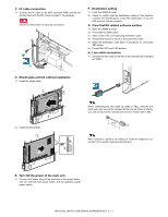
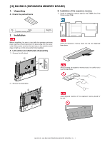
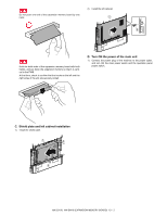
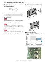
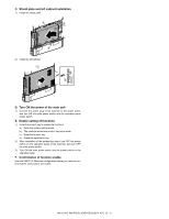
C. I/F cable connection 1) Connect the I/F cable to the MFP controller PWB, and fix the binding band with the M3 screw included in the package. Check to confirm that it is securely connected. 2 1 F. Destination setting 1) Enter the SIM26-6 mode. 2) Check to confirm that the destination setting of the machine matches the specifications of the FAX destination. If not, the FAX may not function properly. G. Clear theFAX related software swithes 1) Enter the SIM66-2 mode. 2) Press DEST CODE button. 3) Take a note of the corresponding destination code. 4) Press BACK button to return to the code entry mode. 5) Enter the destination code taken in procedure 3), and press SET button. 6) Press EXECUTE and YES buttons. H. Line cable connection 1) Connect the line cable on the line to the modular jack indicated as "LINE." D. Shield plate and left cabinet installation 1) Install the shield plate. 1 2 2 2) Install the left cabinet. 1 2 When connecting the line cable (to LINE or TEL), wind the line cable two turns around the included ferrite core as shown in the figure, and connect to the modular jack which is marked with "LINE." About 10 cm After connection, perform the setting of "External telephone connection" of the system setting (administrator). E. Turn ON the power of the main unit 1) Connect the power plug of the machine to the power outlet, and turn ON the main power switch and the operation panel power switch. MX-2310U MX-FX11 (FACSIMILE EXPANSION KIT) 9 - 2
-
 1
1 -
2
-
3
-
4
-
5
-
6
-
7
-
8
-
9
-
10
-
11
-
12
-
13
-
14
-
15
-
16
-
17
-
18
-
19
-
20
-
21
-
22
-
23
-
24
-
25
-
26
-
27
-
28
-
29
-
30
-
31
-
32
-
33
-
34
-
35
-
36
-
37
-
38
-
39
-
40
-
41
-
42
-
43
-
44
-
45
-
46
-
47
-
48
-
49
-
50
-
51
-
 52
52 -
 53
53 -
 54
54 -
 55
55 -
 56
56 -
 57
57 -
 58
58 -
 59
59 -
 60
60 -
 61
61 -
 62
62 -
63
-
64
-
65
-
66
-
67
-
68
-
69
-
70
-
71
-
72
-
73
-
74
-
75
-
76
 |
 |
