Sharp MX-2310U Installation Manual - Page 53
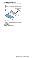
E. Turn ON the power of the main unit, power switch.
 |
View all Sharp MX-2310U manuals
Add to My Manuals
Save this manual to your list of manuals |
Page 53 highlights
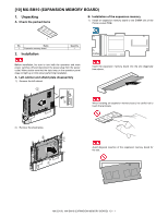
2) Attach the punch position label (for the scanner). Fit with the corner R. No clearance First label Second label Label attachment reference * Corner of the upper cabinet bottom Fit with the corner R. 3) Attach the punch position label (for the RSPF). R2.5 line of tangency Ridge line R2.5 E. Turn ON the power of the main unit 1) Connect the power plug of the machine to the power outlet, and turn ON the main power switch and the operation panel power switch. MX-2310U MX-PN11A/B/C/D (PUNCH MODULE) 7 - 3
-
 1
1 -
2
-
3
-
4
-
5
-
6
-
7
-
8
-
9
-
10
-
11
-
12
-
13
-
14
-
15
-
16
-
17
-
18
-
19
-
20
-
21
-
22
-
23
-
24
-
25
-
26
-
27
-
28
-
29
-
30
-
31
-
32
-
33
-
34
-
35
-
36
-
37
-
38
-
39
-
40
-
41
-
42
-
43
-
44
-
45
-
46
-
47
-
 48
48 -
 49
49 -
 50
50 -
 51
51 -
 52
52 -
 53
53 -
 54
54 -
 55
55 -
 56
56 -
 57
57 -
 58
58 -
59
-
60
-
61
-
62
-
63
-
64
-
65
-
66
-
67
-
68
-
69
-
70
-
71
-
72
-
73
-
74
-
75
-
76
 |
 |

MX-2310U
MX-PN11A/B/C/D (PUNCH MODULE)
7 – 3
2)
Attach the punch position label (for the scanner).
3)
Attach the punch position label (for the RSPF).
E.
Turn ON the power of the main unit
1)
Connect the power plug of the machine to the power outlet,
and turn ON the main power switch and the operation panel
power switch.
First label
Second label
Fit with the corner R.
Label attachment reference
Fit with the corner R.
* Corner of the upper
cabinet bottom
No clearance
Ridge line R2.5
R2.5 line of tangency