Sharp MX-2310U Installation Manual - Page 55
B. Installation of the paper exit tray, C. Turn ON the power of the main unit, D. Tray setting
 |
View all Sharp MX-2310U manuals
Add to My Manuals
Save this manual to your list of manuals |
Page 55 highlights
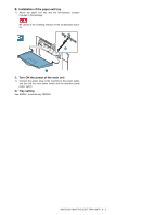
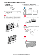
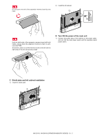
B. Installation of the paper exit tray 1) Attach the paper exit tray and the full-detection actuator included in the package. Be careful of the installing direction of the full detection actuator. 2 1 C. Turn ON the power of the main unit 1) Connect the power plug of the machine to the power outlet, and turn ON the main power switch and the operation panel power switch. D. Tray setting Use SIM26-1 to set the tray YES/NO. MX-2310U MX-TR12 (EXIT TRAY UNIT) 8 - 2
-
 1
1 -
2
-
3
-
4
-
5
-
6
-
7
-
8
-
9
-
10
-
11
-
12
-
13
-
14
-
15
-
16
-
17
-
18
-
19
-
20
-
21
-
22
-
23
-
24
-
25
-
26
-
27
-
28
-
29
-
30
-
31
-
32
-
33
-
34
-
35
-
36
-
37
-
38
-
39
-
40
-
41
-
42
-
43
-
44
-
45
-
46
-
47
-
48
-
49
-
 50
50 -
 51
51 -
 52
52 -
 53
53 -
 54
54 -
 55
55 -
 56
56 -
 57
57 -
 58
58 -
 59
59 -
 60
60 -
61
-
62
-
63
-
64
-
65
-
66
-
67
-
68
-
69
-
70
-
71
-
72
-
73
-
74
-
75
-
76
 |
 |

MX-2310U
MX-TR12 (EXIT TRAY UNIT)
8 – 2
B.
Installation of the paper exit tray
1)
Attach the paper exit tray and the full-detection actuator
included in the package.
Be careful of the installing direction of the full detection actua-
tor.
C.
Turn ON the power of the main unit
1)
Connect the power plug of the machine to the power outlet,
and turn ON the main power switch and the operation panel
power switch.
D.
Tray setting
Use SIM26-1 to set the tray YES/NO.
1
2