Sharp MX-2310U Installation Manual - Page 56
MX-FX11 (FACSIMILE EXPANSION KIT), 1. Unpacking, A. Check the packed items, 2. Installation, A. FAX
 |
View all Sharp MX-2310U manuals
Add to My Manuals
Save this manual to your list of manuals |
Page 56 highlights
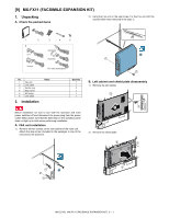
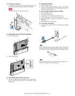
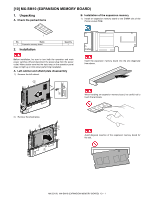
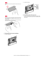
M[9X-]2310MU X-FX11 (FACSIMILE EXPANSION KSIeTr)vice Manual 1. Unpacking A. Check the packed items 2) Hang the Fax unit on the step screw. Fix the Fax unit with the screws which were removed in the step 1). 1 2 6 U.K France 3 4 5 Germany Australia For othe destinations No. 1 Fax unit 2 Line cable 3 Ferrite core 4 Step screw 5 M3 screw 6 Line cable 2. Installation Name Quantity 1 1 2 1 1 1 Before installation, be sure to turn both the operation and main power switches off and disconnect the power plug from the power outlet. Make double sure that the data lamp on the operation panel does not light up or blink when performing installation. A. FAX unit installation 1) Remove the two screws on the rear cabinet of the main unit. Attach the step screw (included in the package) to one of the removed screw positions. 1 2 B. Left cabinet and shield plate disassembly 1) Remove the left cabinet. 2 2 1 1 2) Remove the shield plate. 2 1 1 1 2 1 MX-2310U MX-FX11 (FACSIMILE EXPANSION KIT) 9 - 1
-
 1
1 -
2
-
3
-
4
-
5
-
6
-
7
-
8
-
9
-
10
-
11
-
12
-
13
-
14
-
15
-
16
-
17
-
18
-
19
-
20
-
21
-
22
-
23
-
24
-
25
-
26
-
27
-
28
-
29
-
30
-
31
-
32
-
33
-
34
-
35
-
36
-
37
-
38
-
39
-
40
-
41
-
42
-
43
-
44
-
45
-
46
-
47
-
48
-
49
-
50
-
 51
51 -
 52
52 -
 53
53 -
 54
54 -
 55
55 -
 56
56 -
 57
57 -
 58
58 -
 59
59 -
 60
60 -
 61
61 -
62
-
63
-
64
-
65
-
66
-
67
-
68
-
69
-
70
-
71
-
72
-
73
-
74
-
75
-
76
 |
 |
