TP-Link T1500G-8T T1500G-10PSUN V1 User Guide - Page 83
RSTP Elements, Edge Port, P2P Link
 |
View all TP-Link T1500G-8T manuals
Add to My Manuals
Save this manual to your list of manuals |
Page 83 highlights
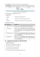
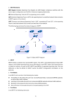
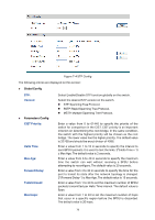
3 The switch compares the resulting BPDU with the BPDU of the desired port whose role you want to determine. If the resulting BPDU takes the precedence over the BPDU of the port, the port is chosen as the designated port and the BPDU of this port is replaced with the resulting BPDU. The port regularly sends out the resulting BPDU; If the BPDU of this port takes the precedence over the resulting BPDU, the BPDU of this port is not replaced and the port is blocked. The port only can receive BPDUs. Table 7-2 Selecting root port and designated port Tips: In a STP with stable topology, only the root port and designated port can forward data, and the other ports are blocked. The blocked ports only can receive BPDUs. RSTP (Rapid Spanning Tree Protocol), evolved from the 802.1D STP standard, enable Ethernet ports to transit their states rapidly. The premises for the port in the RSTP to transit its state rapidly are as follows. The condition for the root port to transit its port state rapidly: The old root port of the switch stops forwarding data and the designated port of the upstream switch begins to forward data. The condition for the designated port to transit its port state rapidly: The designated port is an edge port or connecting to a point-to-point link. If the designated port is an edge port, it can directly transit to forwarding state; if the designated port is connecting to a point-to-point link, it can transit to forwarding state after getting response from the downstream switch through handshake. RSTP Elements Edge Port: Indicates the port connected directly to terminals. P2P Link: Indicates the link between two switches directly connected. MSTP (Multiple Spanning Tree Protocol), compatible with both STP and RSTP and subject to IEEE 802.1s standard, not only enables spanning trees to converge rapidly, but also enables packets of different VLANs to be forwarded along their respective paths so as to provide redundant links with a better load-balancing mechanism. Features of MSTP: MSTP combines VLANs and spanning tree together via VLAN-to-instance mapping table. It binds several VLANs to an instance to save communication cost and network resources. MSTP divides a spanning tree network into several regions. Each region has several internal spanning trees, which are independent of each other. MSTP provides a load-balancing mechanism for the packets transmission in the VLAN. MSTP is compatible with both STP and RSTP. 73
-
 1
1 -
2
-
3
-
4
-
5
-
6
-
7
-
8
-
9
-
10
-
11
-
12
-
13
-
14
-
15
-
16
-
17
-
18
-
19
-
20
-
21
-
22
-
23
-
24
-
25
-
26
-
27
-
28
-
29
-
30
-
31
-
32
-
33
-
34
-
35
-
36
-
37
-
38
-
39
-
40
-
41
-
42
-
43
-
44
-
45
-
46
-
47
-
48
-
49
-
50
-
51
-
52
-
53
-
54
-
55
-
56
-
57
-
58
-
59
-
60
-
61
-
62
-
63
-
64
-
65
-
66
-
67
-
68
-
69
-
70
-
71
-
72
-
73
-
74
-
75
-
76
-
77
-
 78
78 -
 79
79 -
 80
80 -
 81
81 -
 82
82 -
 83
83 -
 84
84 -
 85
85 -
 86
86 -
 87
87 -
 88
88 -
89
-
90
-
91
-
92
-
93
-
94
-
95
-
96
-
97
-
98
-
99
-
100
-
101
-
102
-
103
-
104
-
105
-
106
-
107
-
108
-
109
-
110
-
111
-
112
-
113
-
114
-
115
-
116
-
117
-
118
-
119
-
120
-
121
-
122
-
123
-
124
-
125
-
126
-
127
-
128
-
129
-
130
-
131
-
132
-
133
-
134
-
135
-
136
-
137
-
138
-
139
-
140
-
141
-
142
-
143
-
144
-
145
-
146
-
147
-
148
-
149
-
150
-
151
-
152
-
153
-
154
-
155
-
156
-
157
-
158
-
159
-
160
-
161
-
162
-
163
-
164
-
165
-
166
-
167
-
168
-
169
-
170
-
171
-
172
-
173
-
174
-
175
-
176
-
177
-
178
-
179
-
180
-
181
-
182
-
183
-
184
-
185
-
186
-
187
-
188
-
189
-
190
-
191
-
192
-
193
-
194
-
195
-
196
-
197
-
198
-
199
-
200
-
201
-
202
-
203
-
204
-
205
-
206
-
207
-
208
-
209
-
210
-
211
-
212
-
213
-
214
-
215
-
216
-
217
-
218
-
219
-
220
-
221
-
222
-
223
-
224
-
225
-
226
-
227
-
228
-
229
-
230
-
231
-
232
-
233
-
234
-
235
-
236
-
237
-
238
-
239
-
240
-
241
-
242
 |
 |