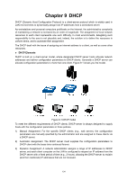
TP-Link T2500-28TCTL-SL5428E T2500-28TCUN V1 User Guide - Page 141
Application Example for DLDP, Shut Mode, Web Refresh State, Web Refresh, Interval, Port Select
 |
View all TP-Link T2500-28TCTL-SL5428E manuals
Add to My Manuals
Save this manual to your list of manuals |
Page 141 highlights
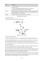
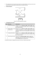
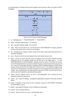
Shut Mode: Web Refresh State: Web Refresh Interval: Port Config Port Select: Select: Port: DLDP State: Protocol State: Link State: Neighbor State: Once detecting a unidirectional link, the port can be shut down in one of the following two modes: • Auto: In this mode, DLDP generates logs and traps and shuts down the corresponding port on detecting unidirectional links, and the DLDP link state transits to Disable. • Manual: In this mode, DLDP only generates logs and traps if it detects unidirectional links, and the operation to shut down the unidirectional link ports is accomplished by the administrator. Enable/Disable the web automatic refresh function. Configure the interval to refresh the web page, ranging from 1 to 100 seconds, and the default value is 5 seconds. Click the Select button to quick-select the corresponding port based on the port number you entered. Select the desired port for configuration. It is multi-optional. Port list of the switch. Enable/Disable DLDP on the selected port. Displays the DLDP protocol state. Displays the state of the links. Displays the state of the selected port's neighbor. Configuration Procedure: Step Operation Description 1 Enable DLDP globally. Required. On the Ethernet OAM→DLDP→DLDP page, configure DLDP State as Enable under the Global Config tab. 2 Enable DLDP on the Required. On the Ethernet OAM→DLDP→DLDP page, specified port. configure DLDP State as Enable on specified port in the Port Config table. 3 Configure Shut Mode. Optional. On the Ethernet OAM→DLDP→DLDP page, configure the Shut Mode as Auto or Manual under the Global Config tab. 4 Reset DLDP state. Optional. On the Ethernet OAM→DLDP→DLDP page, select the specified ports or select all the ports in the Port Config table and click the Reset button to restore their state. 8.7 Application Example for DLDP Network requirements 1. Device A and Device B are connected through two fiber pairs, which are cross-connected, as shown in Figure 8-13. 131
-
 1
1 -
2
-
3
-
4
-
5
-
6
-
7
-
8
-
9
-
10
-
11
-
12
-
13
-
14
-
15
-
16
-
17
-
18
-
19
-
20
-
21
-
22
-
23
-
24
-
25
-
26
-
27
-
28
-
29
-
30
-
31
-
32
-
33
-
34
-
35
-
36
-
37
-
38
-
39
-
40
-
41
-
42
-
43
-
44
-
45
-
46
-
47
-
48
-
49
-
50
-
51
-
52
-
53
-
54
-
55
-
56
-
57
-
58
-
59
-
60
-
61
-
62
-
63
-
64
-
65
-
66
-
67
-
68
-
69
-
70
-
71
-
72
-
73
-
74
-
75
-
76
-
77
-
78
-
79
-
80
-
81
-
82
-
83
-
84
-
85
-
86
-
87
-
88
-
89
-
90
-
91
-
92
-
93
-
94
-
95
-
96
-
97
-
98
-
99
-
100
-
101
-
102
-
103
-
104
-
105
-
106
-
107
-
108
-
109
-
110
-
111
-
112
-
113
-
114
-
115
-
116
-
117
-
118
-
119
-
120
-
121
-
122
-
123
-
124
-
125
-
126
-
127
-
128
-
129
-
130
-
131
-
132
-
133
-
134
-
135
-
 136
136 -
 137
137 -
 138
138 -
 139
139 -
 140
140 -
 141
141 -
 142
142 -
 143
143 -
 144
144 -
 145
145 -
 146
146 -
147
-
148
-
149
-
150
-
151
-
152
-
153
-
154
-
155
-
156
-
157
-
158
-
159
-
160
-
161
-
162
-
163
-
164
-
165
-
166
-
167
-
168
-
169
-
170
-
171
-
172
-
173
-
174
-
175
-
176
-
177
-
178
-
179
-
180
-
181
-
182
-
183
-
184
-
185
-
186
-
187
-
188
-
189
-
190
-
191
-
192
-
193
-
194
-
195
-
196
-
197
-
198
-
199
-
200
-
201
-
202
-
203
-
204
-
205
-
206
-
207
-
208
-
209
-
210
-
211
-
212
-
213
-
214
-
215
-
216
-
217
-
218
-
219
-
220
-
221
-
222
-
223
-
224
-
225
-
226
-
227
-
228
-
229
-
230
-
231
-
232
-
233
-
234
-
235
-
236
-
237
-
238
-
239
-
240
-
241
-
242
-
243
-
244
-
245
-
246
-
247
-
248
-
249
-
250
-
251
-
252
-
253
-
254
-
255
-
256
-
257
-
258
-
259
-
260
-
261
-
262
-
263
-
264
-
265
-
266
-
267
-
268
-
269
-
270
-
271
-
272
-
273
-
274
-
275
-
276
-
277
-
278
-
279
-
280
-
281
-
282
-
283
-
284
-
285
-
286
-
287
-
288
-
289
-
290
-
291
-
292
-
293
-
294
-
295
-
296
-
297
-
298
-
299
-
300
-
301
-
302
-
303
-
304
-
305
-
306
-
307
-
308
-
309
-
310
-
311
-
312
-
313
-
314
-
315
-
316
 |
 |
