TP-Link T2500-28TCTL-SL5428E T2500-28TCUN V1 User Guide - Page 155
Multicast Address Table, VLAN ID, Multicast IP, IGMP Snooping, MLD Snooping
 |
View all TP-Link T2500-28TCTL-SL5428E manuals
Add to My Manuals
Save this manual to your list of manuals |
Page 155 highlights
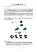
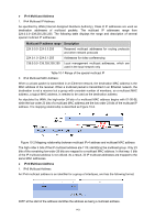
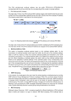
The IPv6 solicited-node multicast address has the prefix FF02:0:0:0:0:1:FF00:0000/104 concatenated with the 24 low-order bits of a corresponding IPv6 unicast or anycast address. 2. IPv6 Multicast MAC Address The high-order 16 bits of an IPv6 multicast MAC address begins with 0x3333 while the low-order 32 bits of an IPv6 multicast MAC address are the low-order 32 bits of the IPv6 multicast IP address. The mapping relationship is described as the following figure: Figure 10-3 Mapping relationship between multicast IPv6 address and multicast IPv6 MAC address The high-order 16 bits of the IP multicast address are 0x3333, identifying the IPv6 multicast group. The low-order 32 bits of the IPv6 multicast IP address are mapped to the multicast MAC address. Multicast Address Table The switch is forwarding multicast packets based on the multicast address table. As the transmission of multicast packets cannot span the VLAN, the first part of the multicast address table is VLAN ID, based on which the received multicast packets are forwarded in the VLAN owning the receiving port. The multicast address table is not mapped to an egress port but a group port list. When forwarding a multicast packet, the switch looks up the multicast address table based on the destination multicast address of the multicast packet. If the corresponding entry cannot be found in the table, the switch will broadcast the packet in the VLAN owning the receiving port. If the corresponding entry can be found in the table, it indicates that the destination address should be a group port list, so the switch will duplicate this multicast data and deliver each port one copy. The general format of the multicast address table is described as Figure 10-4 below. VLAN ID Multicast IP Port Figure 10-4 Multicast Address Table IGMP Snooping In the network, the hosts apply to the near router for joining (leaving) a multicast group by sending IGMP (Internet Group Management Protocol) messages. When the up-stream device forwards down the multicast data, the switch is responsible for sending them to the hosts. IGMP Snooping is a multicast control mechanism, which can be used on the switch for dynamic registration of the multicast group. The switch, running IGMP Snooping, manages and controls the multicast group via listening to and processing the IGMP messages transmitted between the hosts and the multicast router, thereby effectively prevents multicast groups being broadcasted in the network. MLD Snooping Multicast Listener Discovery(MLD)snooping is applied for efficient distribution of IPv6 multicast data to clients and routers in a Layer 2 network. With MLD snooping, IPv6 multicast data is 145
-
 1
1 -
2
-
3
-
4
-
5
-
6
-
7
-
8
-
9
-
10
-
11
-
12
-
13
-
14
-
15
-
16
-
17
-
18
-
19
-
20
-
21
-
22
-
23
-
24
-
25
-
26
-
27
-
28
-
29
-
30
-
31
-
32
-
33
-
34
-
35
-
36
-
37
-
38
-
39
-
40
-
41
-
42
-
43
-
44
-
45
-
46
-
47
-
48
-
49
-
50
-
51
-
52
-
53
-
54
-
55
-
56
-
57
-
58
-
59
-
60
-
61
-
62
-
63
-
64
-
65
-
66
-
67
-
68
-
69
-
70
-
71
-
72
-
73
-
74
-
75
-
76
-
77
-
78
-
79
-
80
-
81
-
82
-
83
-
84
-
85
-
86
-
87
-
88
-
89
-
90
-
91
-
92
-
93
-
94
-
95
-
96
-
97
-
98
-
99
-
100
-
101
-
102
-
103
-
104
-
105
-
106
-
107
-
108
-
109
-
110
-
111
-
112
-
113
-
114
-
115
-
116
-
117
-
118
-
119
-
120
-
121
-
122
-
123
-
124
-
125
-
126
-
127
-
128
-
129
-
130
-
131
-
132
-
133
-
134
-
135
-
136
-
137
-
138
-
139
-
140
-
141
-
142
-
143
-
144
-
145
-
146
-
147
-
148
-
149
-
 150
150 -
 151
151 -
 152
152 -
 153
153 -
 154
154 -
 155
155 -
 156
156 -
 157
157 -
 158
158 -
 159
159 -
 160
160 -
161
-
162
-
163
-
164
-
165
-
166
-
167
-
168
-
169
-
170
-
171
-
172
-
173
-
174
-
175
-
176
-
177
-
178
-
179
-
180
-
181
-
182
-
183
-
184
-
185
-
186
-
187
-
188
-
189
-
190
-
191
-
192
-
193
-
194
-
195
-
196
-
197
-
198
-
199
-
200
-
201
-
202
-
203
-
204
-
205
-
206
-
207
-
208
-
209
-
210
-
211
-
212
-
213
-
214
-
215
-
216
-
217
-
218
-
219
-
220
-
221
-
222
-
223
-
224
-
225
-
226
-
227
-
228
-
229
-
230
-
231
-
232
-
233
-
234
-
235
-
236
-
237
-
238
-
239
-
240
-
241
-
242
-
243
-
244
-
245
-
246
-
247
-
248
-
249
-
250
-
251
-
252
-
253
-
254
-
255
-
256
-
257
-
258
-
259
-
260
-
261
-
262
-
263
-
264
-
265
-
266
-
267
-
268
-
269
-
270
-
271
-
272
-
273
-
274
-
275
-
276
-
277
-
278
-
279
-
280
-
281
-
282
-
283
-
284
-
285
-
286
-
287
-
288
-
289
-
290
-
291
-
292
-
293
-
294
-
295
-
296
-
297
-
298
-
299
-
300
-
301
-
302
-
303
-
304
-
305
-
306
-
307
-
308
-
309
-
310
-
311
-
312
-
313
-
314
-
315
-
316
 |
 |
