Toshiba Portege M780 PPM78C-005006 Users Manual Canada; English - Page 44
Underside, LAN active indicator, orange
 |
View all Toshiba Portege M780 PPM78C-005006 manuals
Add to My Manuals
Save this manual to your list of manuals |
Page 44 highlights
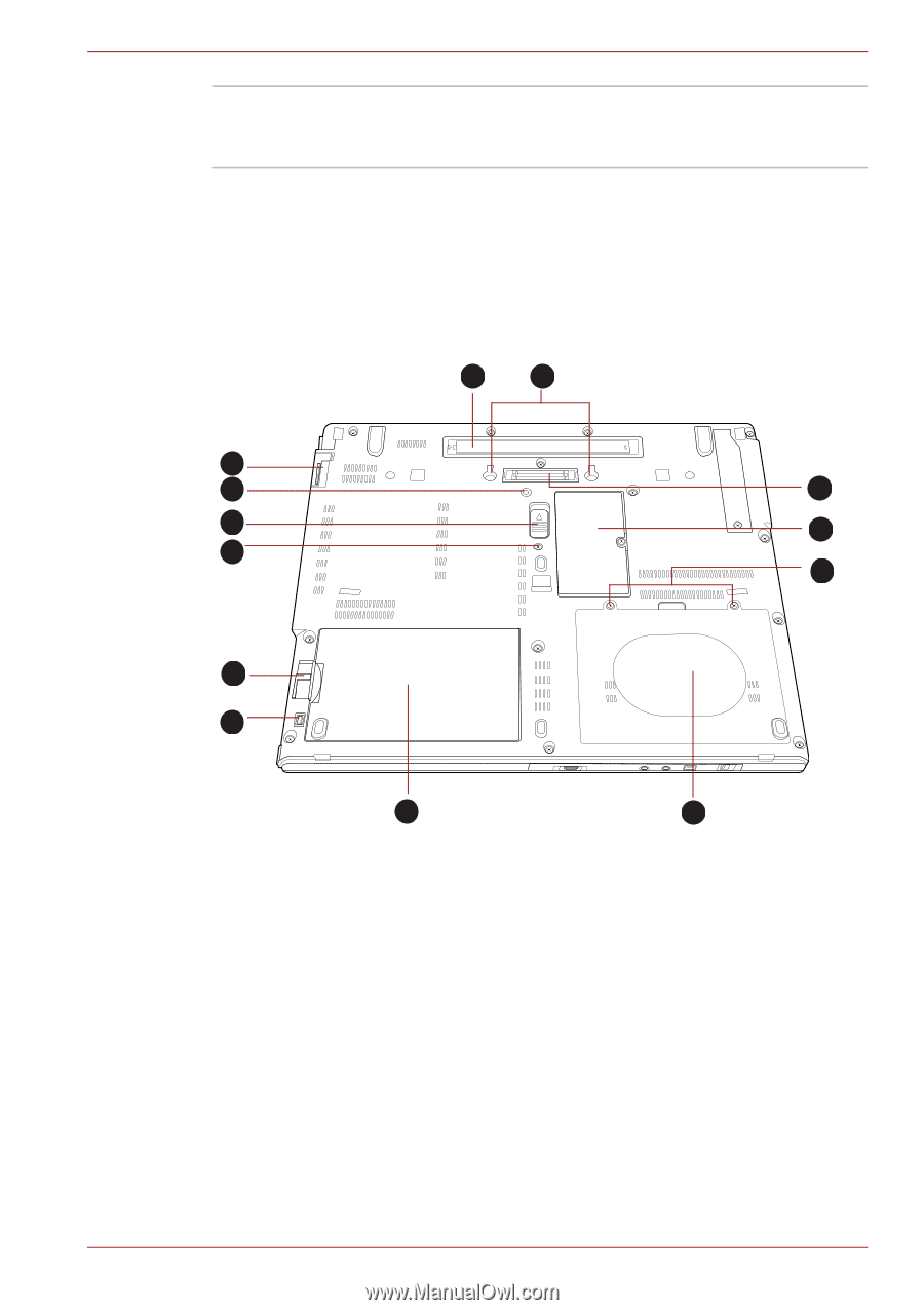
The Grand Tour LAN active indicator This indicator may glow orange when the (orange) computer is connected to a LAN and the LAN is functioning properly. Underside The following figure shows the underside of the computer. You should ensure that the display is closed before the computer is turned over to avoid causing any damage. 13 1 9 12 2 10 3 11 4 6 7 8 5 1. Notches 8. Battery pack 2. Docking port 3. Memory module slot 9. Ultra Slim Bay 10. Ultra Slim Bay latch 4. HDD pack cover screws 5. Hard disk drive cover 11. Ultra Slim Bay lock screw (lock position) 12. Ultra Slim Bay lock screw (unlock position) 6. Battery release latch 7. Battery lock 13. Reserve Pen Figure 2-5 The underside of the computer User's Manual 2-7
-
 1
1 -
2
-
3
-
4
-
5
-
6
-
7
-
8
-
9
-
10
-
11
-
12
-
13
-
14
-
15
-
16
-
17
-
18
-
19
-
20
-
21
-
22
-
23
-
24
-
25
-
26
-
27
-
28
-
29
-
30
-
31
-
32
-
33
-
34
-
35
-
36
-
37
-
38
-
 39
39 -
 40
40 -
 41
41 -
 42
42 -
 43
43 -
 44
44 -
 45
45 -
 46
46 -
 47
47 -
 48
48 -
 49
49 -
50
-
51
-
52
-
53
-
54
-
55
-
56
-
57
-
58
-
59
-
60
-
61
-
62
-
63
-
64
-
65
-
66
-
67
-
68
-
69
-
70
-
71
-
72
-
73
-
74
-
75
-
76
-
77
-
78
-
79
-
80
-
81
-
82
-
83
-
84
-
85
-
86
-
87
-
88
-
89
-
90
-
91
-
92
-
93
-
94
-
95
-
96
-
97
-
98
-
99
-
100
-
101
-
102
-
103
-
104
-
105
-
106
-
107
-
108
-
109
-
110
-
111
-
112
-
113
-
114
-
115
-
116
-
117
-
118
-
119
-
120
-
121
-
122
-
123
-
124
-
125
-
126
-
127
-
128
-
129
-
130
-
131
-
132
-
133
-
134
-
135
-
136
-
137
-
138
-
139
-
140
-
141
-
142
-
143
-
144
-
145
-
146
-
147
-
148
-
149
-
150
-
151
-
152
-
153
-
154
-
155
-
156
-
157
-
158
-
159
-
160
-
161
-
162
-
163
-
164
-
165
-
166
-
167
-
168
-
169
-
170
-
171
-
172
-
173
-
174
-
175
-
176
-
177
-
178
-
179
-
180
-
181
-
182
-
183
-
184
-
185
-
186
-
187
-
188
-
189
-
190
-
191
-
192
-
193
-
194
-
195
-
196
-
197
-
198
-
199
-
200
-
201
-
202
-
203
-
204
-
205
-
206
-
207
-
208
-
209
-
210
-
211
-
212
-
213
-
214
-
215
-
216
-
217
-
218
-
219
-
220
-
221
-
222
-
223
-
224
-
225
-
226
-
227
-
228
-
229
-
230
-
231
-
232
-
233
-
234
-
235
-
236
-
237
-
238
-
239
-
240
-
241
-
242
-
243
-
244
-
245
-
246
-
247
-
248
-
249
-
250
-
251
-
252
-
253
-
254
-
255
-
256
-
257
-
258
-
259
-
260
-
261
-
262
-
263
-
264
-
265
-
266
-
267
-
268
 |
 |
User’s Manual
2-7
The Grand Tour
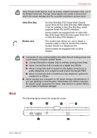
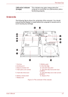
Underside
The following figure shows the underside of the computer. You should
ensure that the display is closed before the computer is turned over to
avoid causing any damage.
Figure 2-5 The underside of the computer
LAN active indicator
(orange)
This indicator may glow orange when the
computer is connected to a LAN and the LAN is
functioning properly.
1
2
3
4
5
6
7
8
9
10
13
12
11
1. Notches
8. Battery pack
2. Docking port
9. Ultra Slim Bay
3. Memory module slot
10. Ultra Slim Bay latch
4. HDD pack cover screws
11. Ultra Slim Bay lock screw (lock
position)
5. Hard disk drive cover
12. Ultra Slim Bay lock screw (unlock
position)
6. Battery release latch
13. Reserve Pen
7. Battery lock